2500_Users_Manual-.pdf - 第27页
L O W P R E S S U R E 2 0 - 5 0 P S I H I G H P R E S S U R E 6 5 - 8 5 P S I A J S SHIFT B K T DEL C L U D M V E N W F O X SHIFT G P Y H Q Z I R ENT ER 1 4 7 2 5 8 3 6 9 0 LO WER CASE RESE T STO P CAL STA RT ON 176 4-4 …
Introduction
Front
Panel
—
The
front
panel
includes
an
alphanumeric
keyboard
for
text
and
data
entry,
and
a
4-line,
160-character
back-lit
display
for
communicating
prompts
to
the
operator.
This
panel
is
used
primarily
for
running
diagnostics
and
invoking
special
handler/labeler
firmware
commands.
(Refer
to
page
1-11
for
more
detailed
information.)
Output
Tube
Holders
—
By
default,
the
right
tube
holder
(tube
1)
accepts
all
devices
that
have
passed
the
programming/testing
operation.
The
left
tube
(tube
2)
holds
any
devices
that
have
not
passed
the
system
programming
and
verify
cycles.
Main
Plate
—
The
primary
surface
on
which
the
track,
beam,
and
other
components
described
above
are
mounted.
The
system
power
supply
and
controlling
electronics
boards
are
located
in
the
base,
under
the
main
plate.
Two
corner
screws
attach
the
hinged
main
plate
to
the
base.
With
these
screws
removed,
the
plate
can
be
raised
to
allow
access
to
service
the
system
electronics.
CAUTION:
To
prevent
main
plate
from
accidentally
falling
shut,
be
careful
not
to
jar
it
when
it
is
raised.
Ground
Wrist
Strap
Connector
—
The
operator's
antistatic
wrist
strap
is
inserted
in
this
connector.
CAUTION:
The
devices
being
processed
through
the
ProMaster
2500
and
components
on
Se
system's
circuit
boards
are
static
sensitive
and
may
be
damaged
by
electrostatic
discharge
(ESD).
To
help
eliminate
damage
from
ESD,
operators
and
service
personnel
should
wear
an
antistatic
wrist
strap
while
using
the
equipment.
The
wrist
strap
should
be
connected
to
the
grounding
plug.
It
should
contain
a
IM
ohm
(minimum
value)
to
10M
ohm
(maximum
value)
isolating
resistor.
Emergency
Stop
Button
(E-stop)
—
A
red
emergency
stop
button
is
located
below
the
disk
drive
on
the
right
side
of
the
front
panel.
Pressing
this
button
will
shut
off
all
input
AC
power
to
the
2500,
immediately
stopping
all
handler
movement
and
turning
the
programmer
off.
Devices
in
the
middle
of
the
programming
and
labeling
process
(those
in
programming
module
sockets
and
waiting
in
the
middle
track)
will
be
in
an
undefined
state.
All
devices
in
the
module
sockets
and
tracks
should
be
removed
from
the
2500
and
discarded.
Power
to
the
PC
is
not
affected,
but
TaskLink's
Job
Status
report
statistics
will
not
be
accurate
because
the
information
displayed
on
this
screen
includes
devices
that
were
in
the
middle
of
the
processing
cycle
when
the
power
was
turned
off.
Remove
all
devices
from
the
track
sections
and
programming
modules
before
turning
the
power
back
on.
To
restore
power,
pull
out
on
the
red
E-stop
button.
The
Task
that
was
running
when
the
button
was
pressed
must
be
restarted.
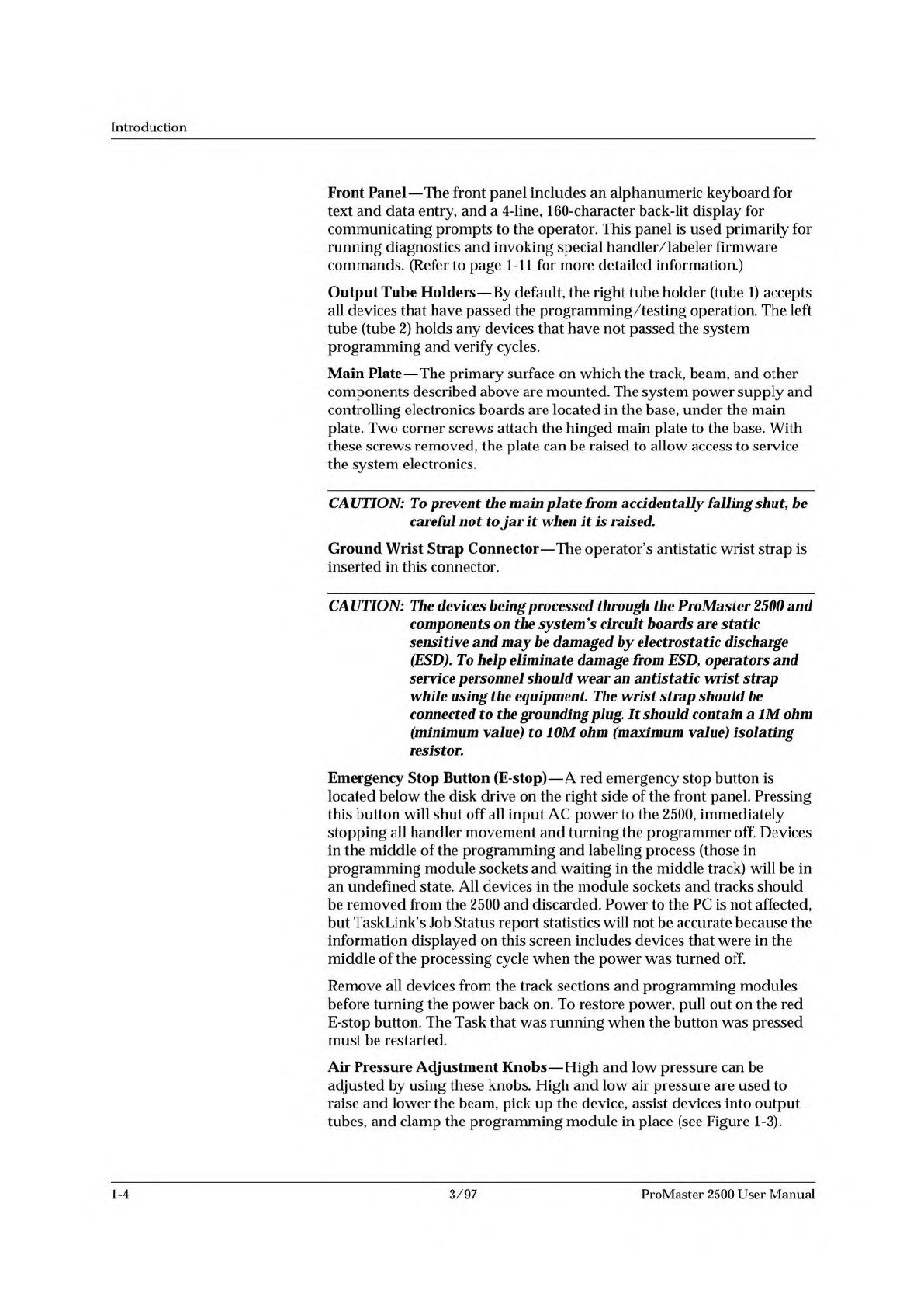
Air
Pressure
Adjustment
Knobs
—
High
and
low
pressure
can
be
adjusted
by
using
these
knobs.
High
and
low
air
pressure
are
used
to
raise
and
lower
the
beam,
pick
up
the
device,
assist
devices
into
output
tubes,
and
clamp
the
programming
module
in
place
(see
Figure
1-3).
1-4
3/97
ProMaster
2500
User
Manual
L
O
W
P
R
E
S
S
U
R
E
2
0
-
5
0
P
S
I
H
I
G
H
P
R
E
S
S
U
R
E
6
5
-
8
5
P
S
I
A
J
S
SHIFT
B
K
T
DEL
C
L
U
D
M
V
E
N
W
F
O
X
SHIFT
G
P
Y
H
Q
Z
I
R
ENTER
1
4
7
2
5
8
3
6
9
0
LOWER
CASE
RESET
STOP
CAL
START
ON
1764-4
HIGH PRESSURE
ADJUSTMENT KNOB
LOW PRESSURE
ADJUSTMENT KNOB
Introduction
Figure
1-3
System
Air
Adjustment
Knobs
Back
of
2500
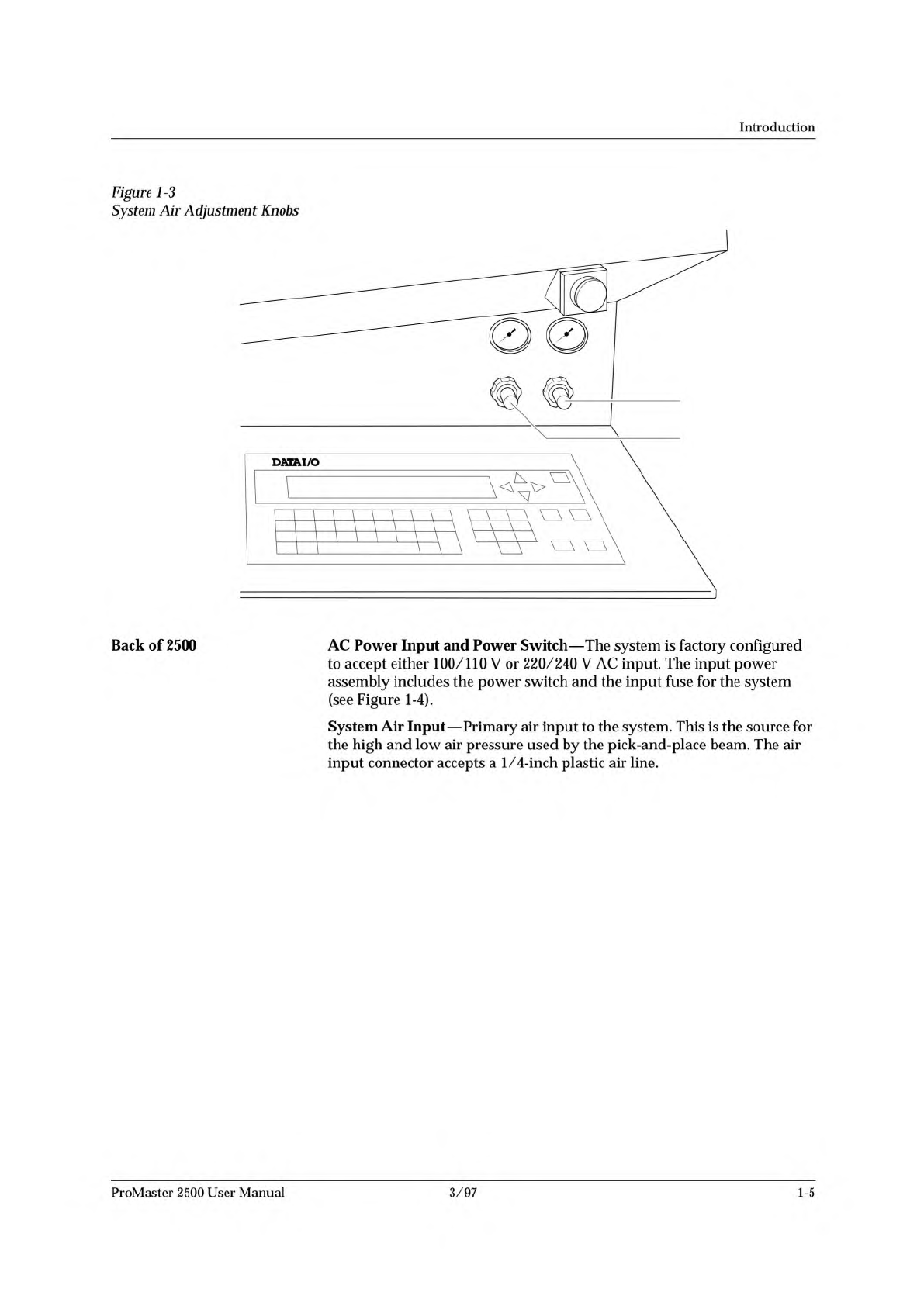
AC
Power
Input
and
Power
Switch
—
The
system
is
factory
configured
to
accept
either
100/110
V
or
220/240
V
AC
input.
The
input
power
assembly
includes
the
power
switch
and
the
input
fuse
for
the
system
(see
Figure
1-4).
System
Air
Input
—
Primary
air
input
to
the
system.
This
is
the
source
for
the
high
and
low
air
pressure
used
by
the
pick-and-place
beam.
The
air
input
connector
accepts
a
1/4-inch
plastic
air
line.
ProMaster
2500
User
Manual
3/97
1-5
1759-2
POWER SWITCH
AIR INPUT
REMOTE RS232
PROGRAMMER RS232
HANDLER PORT
AC POWER
INLET
1760-3
CABLE HARNESS
GUIDE
BEAM HEAD
BEAM TRAVERSE
MOTOR
INPUT TUBE
HOLDER
TRACK WIDTH
ADJUSTMENT
KNOB
REAR CARRIAGE SHAFT
LEAD SCREW
FRONT CARRIAGE SHAFT
OUTPUT TUBE
HOLDER (1 of 2)
BEAM CARRIAGE
MAIN PLATE
LABELER
LABEL
APPLICATION
AREA
DEVICE RECESS
(2 of 2)
DEVICE RECESS (1 of 2)
LABEL SUPPLY
REEL
PROGRAMMING
STATION
E-STOP
BUTTON
Introduction
RS-232
Ports
—
Two
serial
ports
are
used
to
connect
the
2500
with
the
PC
that
is
running
TaskLink.
A
third
port
is
available
for
running
diagnostic
tests.
Figure
1-4
External
Features
on
the
ProMaster
2500
(rear
view)
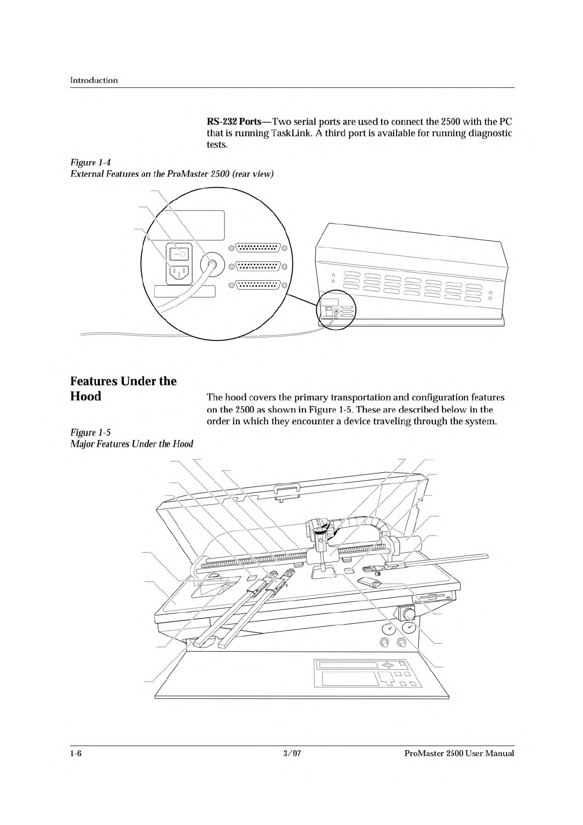
Features
Under
the
Hood
The
hood
covers
the
primary
transportation
and
configuration
features
on
the
2500
as
shown
in
Figure
1-5.
These
are
described
below
in
the
order
in
which
they
encounter
a
device
traveling
through
the
system.
Figure
1-5
Major
Features
Under
the
Hood
1-6
3/97
ProMaster
2500
User
Manual