00196962-04-BA-SX12-V2-EN.pdf - 第110页
3 Technical data and assemblies User manual SIPLACE SX1/SX2 3.5 Placement head From software version SC 706.1 SP1 Version 10/2014 110 3.5.1.3 Sensor for the component reject bin 3 3.5.2 V acuum pump 3.5.2.1 Safety instru…
User manual SIPLACE SX1/SX2 3 Technical data and assemblies
From software version SC 706.1 SP1 Version 10/2014 3.5 Placement head
109
3.5.1.2 Technical data SIPLACE SpeedStar (C&P20)
3
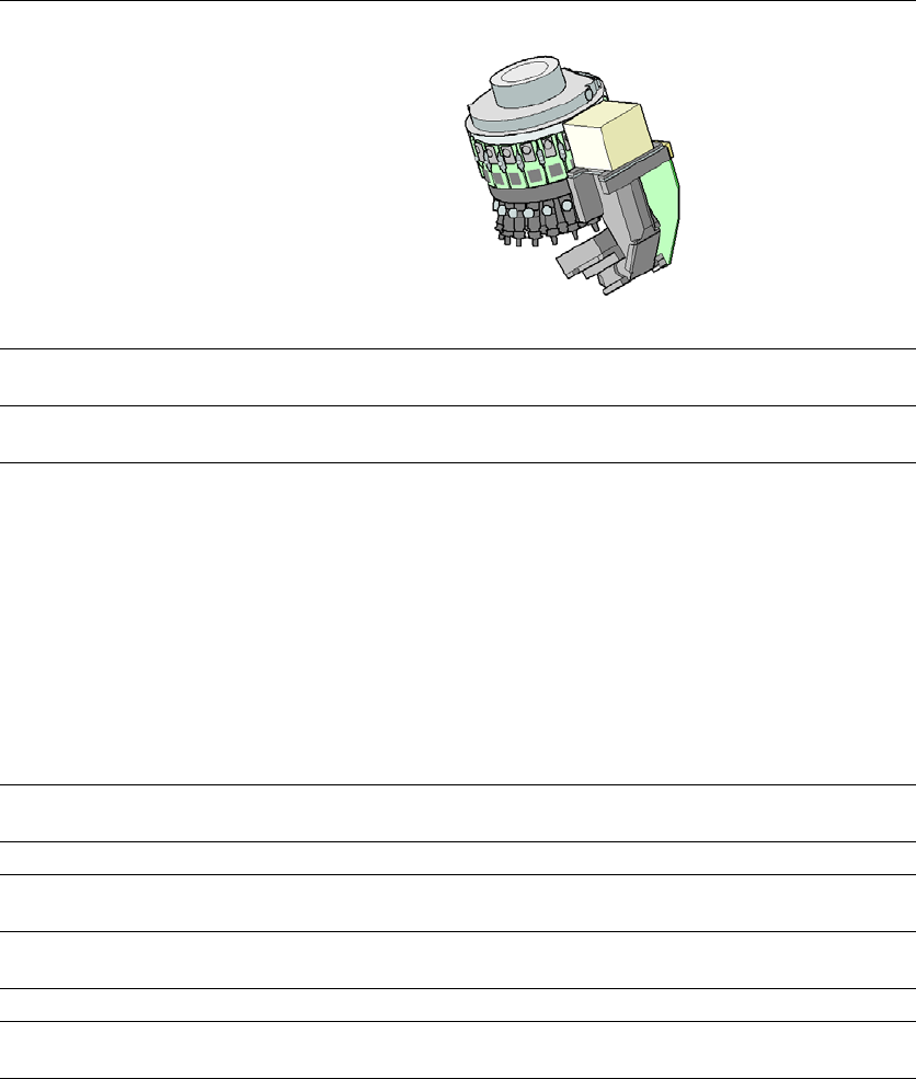
SIPLACE SpeedStar (C&P20)
with component camera
type 23
with component camera type 41
Component range
*a
*)a Please note that the placeable component range is also affected by the pad geometry, the customer-spe-
cific standards, the component packaging tolerances and the component tolerances.
01005 to 2220, Melf, SOT,
SOD
03015 mmto 2220, Melf, SOT,
SOD, Bare-Die, Flip-Chip
Component spec.
Max. height
Min. lead pitch
Min. lead width
Min. ball pitch
Min. ball diameter
Min. dimensions
Max. dimensions
Max. weight
4 mm
0.25 mm
0.1 mm
0.4 mm
0.2 mm
0.4 mm x 0.2 mm
6 mm x 6 mm
1 g
4 mm
0.08 mm
0.03 mm
0.10 mm
0.05 mm
0.12 mm x 0.12 mm
6 mm x 6 mm
1 g
Programmable set-down
force
1.5 - 4.5 N 1.5 - 4.5 N
Nozzle types 10xx, 11xx, 12xx 10xx, 11xx, 12xx
X/Y accuracy
*b
*)b The SIPLACE benchmark value is measured during the machine acceptance tests. It corresponds to the
conditions set out in the SIPLACE scope of service and supply.
± 41 µm/3σ
± 55 µm/4σ
± 41 µm/3σ
± 55 µm/4σ
Angular accuracy ± 0.5° / 3σ
± 0.7° / 4σ
± 0.5° / 3σ
± 0.7° / 4σ
Illumination level 5 5
Possible illumination
level settings
256
5
256
5
3 Technical data and assemblies User manual SIPLACE SX1/SX2
3.5 Placement head From software version SC 706.1 SP1 Version 10/2014
110
3.5.1.3 Sensor for the component reject bin
3
3.5.2 Vacuum pump
3.5.2.1 Safety instructions for vacuum pumps
3
3.5.3 Description
Each Collect&Place head has its own vacuum generator, which supplies the holding and place-
ment circuit with the required vacuum. The vacuum generator for the placement heads functions
according to the Venturi principle. When operated together with a vacuum pump, the compressed
air consumption for the SpeedStar (C&P20) head can be reduced considerably. A vacuum pump
can supply up to two SpeedStar (C&P20) heads. Only one vacuum pump can be used at a time.
The running costs will fall according to the energy costs incurred.
3
3
PLEASE NOTE
When using a SpeedStar we recommend that you install the optional sensor for the com-
ponent reject bin. (See also section 6.7
, page 333)
WARNING
Please observe the safety instructions in the user manual supplied.
PLEASE NOTE
The compressed air consumption values can be found in section 3.2.4
, page 98.
User manual SIPLACE SX1/SX2 3 Technical data and assemblies
From software version SC 706.1 SP1 Version 10/2014 3.5 Placement head
111
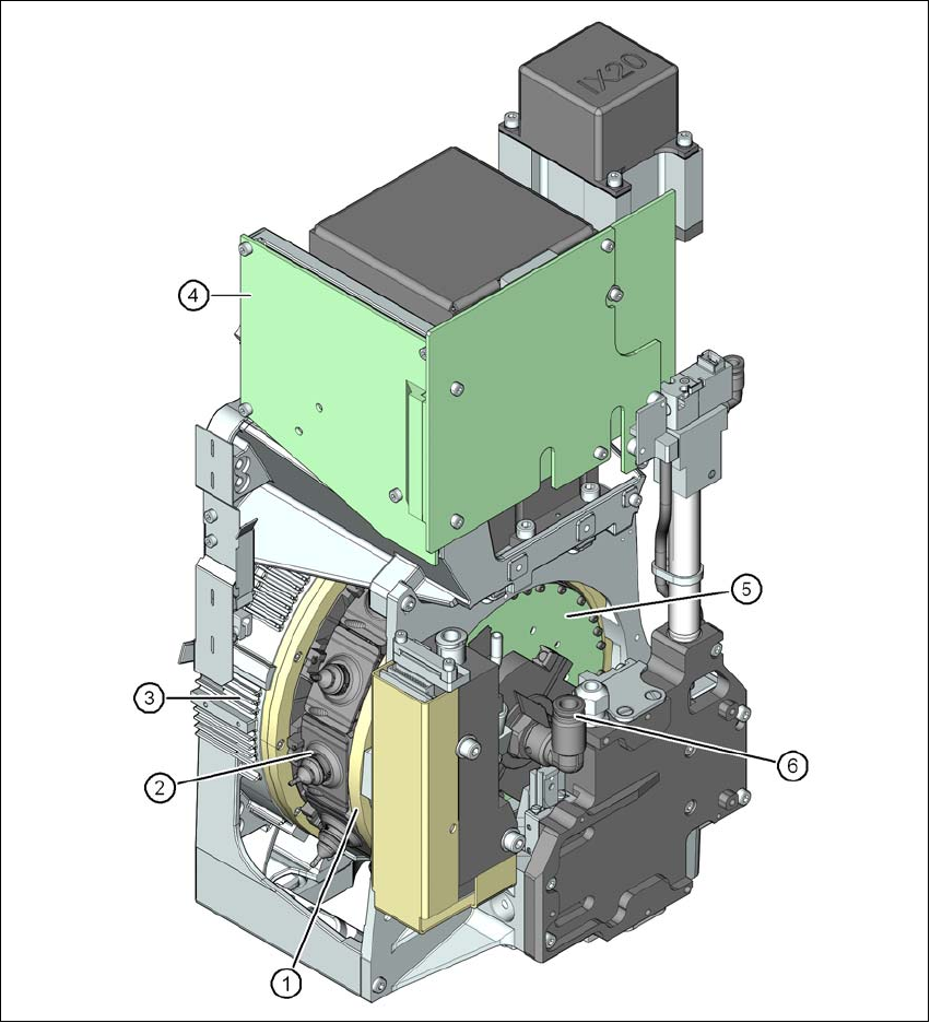
3.5.4 SIPLACE MultiStar CPP
3
Fig. 3.5 - 3 SIPLACE MultiStar - front view, function groups part 1
(1) Star with 12 segments
(2) Segment with integrated DP drive
(3) Torque motor for star drive
(4) Intermediate distributor board
(5) Control board for 12 DP drives
(6) Compressed air connection for the Venturi nozzles in the pickup/placement and holding cir-
cuit