00196962-04-BA-SX12-V2-EN.pdf - 第69页
User manual SIPLACE SX1/SX2 2 Operational safety From software version SC 706.1 SP1 Version 10/2014 2.7 Safety features 69 2.7.2.2 Position of protective switches on the machine 2 Fig. 2.7 - 5 Position of protective swit…
2 Operational safety User manual SIPLACE SX1/SX2
2.7 Safety features From software version SC 706.1 SP1 Version 10/2014
68
2
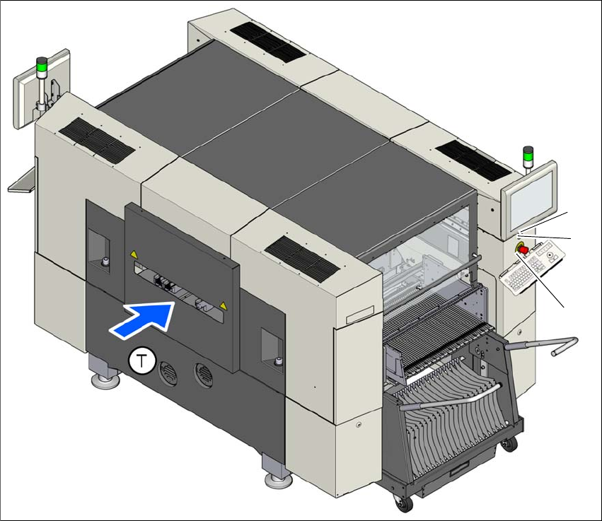
Fig. 2.7 - 4 Position of switches and buttons - View of the PCB input side
(1) EMERGENCY STOP button
(2) Start button
(3) Stop button (black)
(T) PCB transport direction
(3)
(1)
(2)
User manual SIPLACE SX1/SX2 2 Operational safety
From software version SC 706.1 SP1 Version 10/2014 2.7 Safety features
69
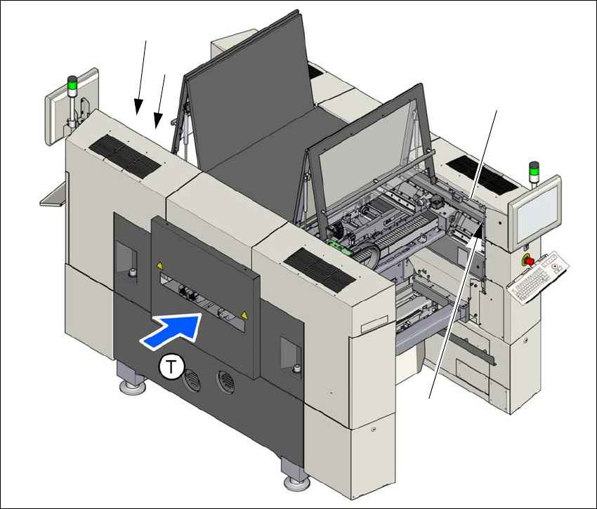
2.7.2.2 Position of protective switches on the machine
2
Fig. 2.7 - 5 Position of protective switches on the machine
(1) Protective cover switch, location 1
(2) Protective cover switch, location 2
(3) Protective switch for bumper detection
(T) PCB transport direction
(2)
(1)
(3)
(3)

2 Operational safety User manual SIPLACE SX1/SX2
2.7 Safety features From software version SC 706.1 SP1 Version 10/2014
70
2.7.2.3 Description of functions
Main switch in OFF position (see item 1 in fig.
2.7 - 3, page 67) 2
The main power switch disconnects the three phases L1, L2, and L3 from the power supply.
2
Main switch in ON position 2
After switching on the main switch, mains voltage is present at the inrush current limiter (A1) and
the 24 V- AC/DC converter is addressed. The "power" LED will shine on the protective contactor
combination (K3). The control computer will start up and supply voltage will be made available with
the exception of the intermediate circuit voltages for the gantry axes (260 V-) and star axes (150 V-
).
Stop button (black) (items 2 and 7 in fig. 2.7 - 3, page 67 and items 3 + 5 in fig. 2.7 - 4, page 68)2
These buttons are used to stop the machine.
Start button (items 3 and 6 in fig. 2.7 - 3, page 67 and items 2 + 4 in fig. 2.7 - 4, page 68) 2
After switching on the main power switch you will be prompted to press the start button in order to
start the machine for placement jobs. The same prompt appears if you open the protective covers
or the press the EMERGENCY STOP button.
DANGER
Lethal voltages!
Incorrect handling of the machine can therefore result in death or severe injury or consid-
erable damage to equipment.
The following components still carry potentially lethal voltages even if the main power
switch is switched off:
– Cable connection terminals L1, L2, and L3 of the Q1 main power switch
– Service socket X98
– F1 automatic circuit breaker for the service socket
– The color of all individual wires, which still carry potentially lethal voltages even if the
main power switch is switched off, is brown.
Always follow the applicable accident prevention and DIN regulations (particularly EN
60204, part 1 or IEC 60204, part 1) and the applicable regulations in your own coun-
try.
The safety door to the power supply must ONLY be opened by appropriately qualified
and trained personnel.