00196962-04-BA-SX12-V2-EN.pdf - 第80页
2 Operational safety User manual SIPLACE SX1/SX2 2.8 Residual voltages and discharge times in the machin e From software version SC 706.1 SP1 Version 10/2014 80 2.8.1 Residual volt ages and discharge tim es after switchi…
User manual SIPLACE SX1/SX2 2 Operational safety
From software version SC 706.1 SP1 Version 10/2014 2.8 Residual voltages and discharge times in the machine
79
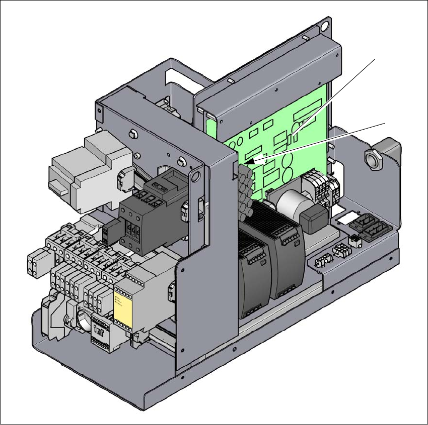
Fig. 2.8 - 2 Measuring points on the power supply unit
(1) Fuse and distributor board (A3)
(2) Rectifier board (A7)
(1)
(2)

2 Operational safety User manual SIPLACE SX1/SX2
2.8 Residual voltages and discharge times in the machine From software version SC 706.1 SP1 Version 10/2014
80
2.8.1 Residual voltages and discharge times after switching off the main switch
2
2.8.2 Residual voltages and discharge times after pressing the EMERGENCY
STOP button
2
Measurement point on the
fuse and distributor board
(A3)
(terminal/pin)
Voltage in
normal mode
Residual voltage if
main switch OFF or
power failure
Discharge
times
XB8a / XB8b; Pin 1 in each case 150 V- < 10 VDC < 2s
X25, Pin 1 42 V- < 10 VDC < 2s
X1A / X1B, Pin1 in each case 24 V- < 10 VDC < 2s
XB4; Pin 6 24 V- < 10 VDC < 2s
Measurement point on the
rectifier board (A7
(terminal/pin)
Voltage in
normal mode
Residual voltage if
main switch OFF or
power failure
Discharge
times
XB7a/XB7b, Pin1 in each case 260 V- < 10 VDC < 2s
At the marked point on the rec-
tifier DC40V-S 42 V- < 10 VDC < 2s
Measurement point on the
fuse and distributor board
(A3)
(terminal/pin)
Voltage in
normal mode
Residual voltage after
EMERGENCY STOP
Discharge
times
XB8a / XB8b; Pin 1 in each case 150 V- < 10 VDC < 2s
XB4; Pin 6 24 V- < 10 VDC < 2s
Measurement point on the
rectifier board (A7
(terminal/pin)
Voltage in
normal mode
Residual voltage after
EMERGENCY STOP
Discharge
times
XB7a/XB7b, Pin1 in each case 260 V- < 10 VDC < 2s
At the marked point on the rec-
tifier DC40V-S 42 V- < 10 VDC < 2s
User manual SIPLACE SX1/SX2 2 Operational safety
From software version SC 706.1 SP1 Version 10/2014 2.9 Disabling the compressed air supply and discharging the pressure
81
2
2.9 Disabling the compressed air supply and discharging
the pressure
The compressed air working pressure of the machine is set to 0.50 ± 0.025 MPa (5.0 ± 0.25 bar).
The position of the compressed air unit is shown at item 1 in fig. 2.9 - 1
, page 82 ) The supply of
compressed air to the machine can be interrupted with the shutoff valve (item 2 in fig. 2.9 - 1
, page
82
).
Use the machine key to release the cover lock.
Lift the cover (see fig. 2.9 - 1, page 82 ).
Turn the lever of the shutoff valve (item 1 of fig. 2.9 - 1, page 82) from the vertical to the hor-
izontal position.
Monitor the operating pressure manometer (item 5 in fig. 2.9 - 1, page 82 ). When the machine
is switched on, the pressure discharges to 0 MPa (0 bar) within 1 minute.
2
CAUTION
Data loss!
To avoid losing data, assess the following criteria before switching off your machine (apart
from in emergencies):
– Has the machine finished transmitting machine, setup and panel data?
– Has the machine finished processing the PCB?
– Has the machine completed the run-up phase?
CAUTION
Interruption to compressed air supply!
When the machine is switched on, do not use the stop valve to interrupt the com-
pressed air supply for more than 30 minutes.
If you need to shut off the pneumatic system for longer in order to carry out preventive
maintenance or servicing work, you must switch the machine off at the main switch
and disconnect it from the power supply.