00196962-04-BA-SX12-V2-EN.pdf - 第71页
User manual SIPLACE SX1/SX2 2 Operational safety From software version SC 706.1 SP1 Version 10/2014 2.7 Safety features 71 Component counter 2 The number of placed componen ts (component count er) can be read on the stat…

2 Operational safety User manual SIPLACE SX1/SX2
2.7 Safety features From software version SC 706.1 SP1 Version 10/2014
70
2.7.2.3 Description of functions
Main switch in OFF position (see item 1 in fig.
2.7 - 3, page 67) 2
The main power switch disconnects the three phases L1, L2, and L3 from the power supply.
2
Main switch in ON position 2
After switching on the main switch, mains voltage is present at the inrush current limiter (A1) and
the 24 V- AC/DC converter is addressed. The "power" LED will shine on the protective contactor
combination (K3). The control computer will start up and supply voltage will be made available with
the exception of the intermediate circuit voltages for the gantry axes (260 V-) and star axes (150 V-
).
Stop button (black) (items 2 and 7 in fig. 2.7 - 3, page 67 and items 3 + 5 in fig. 2.7 - 4, page 68)2
These buttons are used to stop the machine.
Start button (items 3 and 6 in fig. 2.7 - 3, page 67 and items 2 + 4 in fig. 2.7 - 4, page 68) 2
After switching on the main power switch you will be prompted to press the start button in order to
start the machine for placement jobs. The same prompt appears if you open the protective covers
or the press the EMERGENCY STOP button.
DANGER
Lethal voltages!
Incorrect handling of the machine can therefore result in death or severe injury or consid-
erable damage to equipment.
The following components still carry potentially lethal voltages even if the main power
switch is switched off:
– Cable connection terminals L1, L2, and L3 of the Q1 main power switch
– Service socket X98
– F1 automatic circuit breaker for the service socket
– The color of all individual wires, which still carry potentially lethal voltages even if the
main power switch is switched off, is brown.
Always follow the applicable accident prevention and DIN regulations (particularly EN
60204, part 1 or IEC 60204, part 1) and the applicable regulations in your own coun-
try.
The safety door to the power supply must ONLY be opened by appropriately qualified
and trained personnel.

User manual SIPLACE SX1/SX2 2 Operational safety
From software version SC 706.1 SP1 Version 10/2014 2.7 Safety features
71
Component counter 2
The number of placed components (component counter) can be read on the station software. For
more information, refer to the Online Help.
EMERGENCY STOP button with forced locking (item 5 in fig. 2.7 - 3, page 67 and item 1 in fig.
2.7 - 4, page 68) 2
The EMERGENCY STOP button is red and latches in the ON position when pressed. When you
press the EMERGENCY STOP button, the switching contact of the EMERGENCY STOP circuit
opens and the protective contactor combination (K3) trips. The link voltage (260 VDC) for the gan-
try axes and the link voltage (150 VDC) for the star axes is switched off. The servo amplifiers for
the DP and Z axes are still supplied with 42 VDC. The signaling contact of the EMERGENCY
STOP button opens and the message "EMERGENCY STOP pressed" appears on the screen.
The following modules are deactivated:
– PCB conveyor
– PCB clamping
– Width adjustment
– PCB stopper
– Feeder Control Unit
– Safety valve for the tape cutter
2
Protective cover switch 1 and 2 ( item 1 and 2 in fig. 2.7 - 5, page 69) 2
These switches check whether the protective covers are closed. When they are closed, the
EMERGENCY STOP contact and the signaling contact are closed. If one of the covers is opened,
the EMERGENCY STOP contact and the signaling contact will open. Individual components are
disabled or remain enabled (see fig. 2.7 - 8
, page 76 ).
Protective switch for bumper detection (item 3 in fig. 2.7 - 5, page 69) 2
In SIPLACE SX1/SX2 machines, this switch checks whether at least one bumper is present. This
ensures that at least one bumper has been installed again after gantry replacement.
PLEASE NOTE
Placement is interrupted and can then either be continued or canceled once the machine
is working correctly again.
2 Operational safety User manual SIPLACE SX1/SX2
2.7 Safety features From software version SC 706.1 SP1 Version 10/2014
72
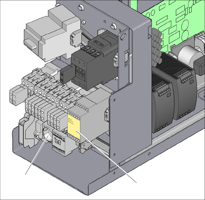
2.7.3 Position of protective contactor combination and service socket
2
Fig. 2.7 - 6 Position of protective contactor combination and service socket
2
(1) Protective contactor combination
(2) Service socket
(2)
(1)