00196962-04-BA-SX12-V2-EN.pdf - 第190页
4 Setting up and commissioning Us er ma nual SIPLACE SX1/SX2 4.1 Transportation and delivery configuration From software ver sion SC 706.1 SP1 Version 10/2014 190 4.1.5.4 Point s that MUST be noted when transporting the …
User manual SIPLACE SX1/SX2 4 Setting up and commissioning
From software version SC 706.1 SP1 Version 10/2014 4.1 Transportation and delivery configuration
189
4
4
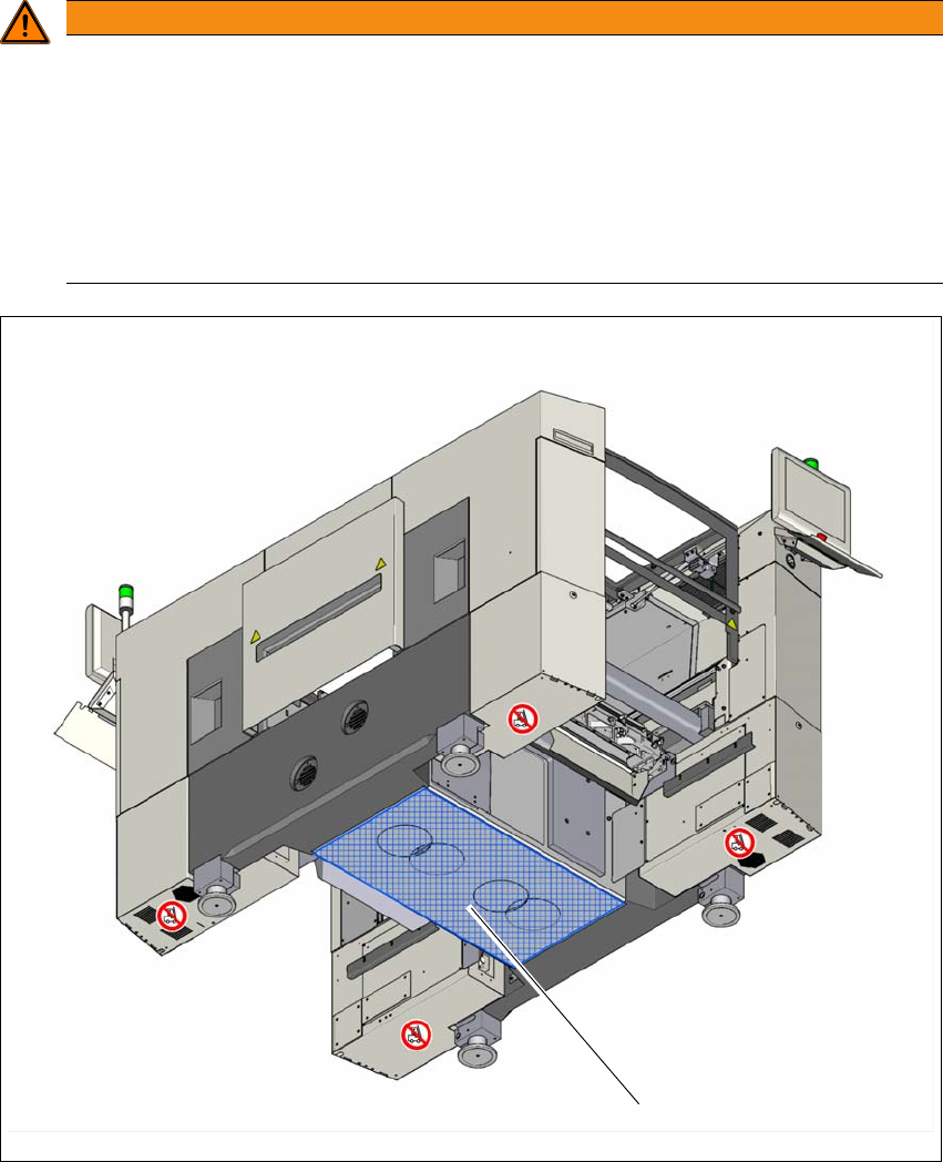
Fig. 4.1 - 3 Contact surfaces - Forks parallel to the direction of PCB transport
(1) Contact surface for fork lift truck forks
WARNING
Risk of damage due to one-sided loading!
One-sided loading of the machine feet e.g. from tilting the machine, can lead to deforma-
tion of the machine feet.
Make sure that the forks are evenly loaded when you lift the machine.
Use a firm support layer between the forks and the machine.
Enlist the help of a second person to watch while you lift the machine and make sure
that the machine does not tip over to one side.
(1)

4 Setting up and commissioning User manual SIPLACE SX1/SX2
4.1 Transportation and delivery configuration From software version SC 706.1 SP1 Version 10/2014
190
4.1.5.4 Points that MUST be noted when transporting the machine
4
WARNING
Risk of damage!
The thread for the machine feet in the machine frame could be damaged by being
dragged along the floor or from impact.
When you are transporting the machine, make sure that all the feet are clear of the
floor.
User manual SIPLACE SX1/SX2 4 Setting up and commissioning
From software version SC 706.1 SP1 Version 10/2014 4.2 Infrastructure at the installation location
191
4.2 Infrastructure at the installation location
4
4.2.1 Recommendations for foundation quality
The foundation on which the machine is installed must be firm and level, as dynamic forces could
cause vibrations when the machine is operated. The degree of vibration depends on the construc-
tion of the foundation. The following are suitable provided that the floor loading parameters, etc.,
are not exceeded:
– Reinforced concrete ceiling constructions, e.g. ceilings in production halls
– Reinforced concrete floor slabs, e.g. concrete floors in production halls without a basement
– Rooms with double floors, provided that a stable foundation is included in the space between
them. The same setup conditions apply to this intermediate foundation, which can be made
from steel girders or concrete.
4.2.1.1 Maximum ground levelness
The floor underneath the machine may not exceed an incline of 0.6%. This corresponds to an in-
cline of 5 mm (in Y direction) and 4 mm (X direction) along a distance of 800 mm
(e.g. the width of a component trolley).
4.2.1.2 Machine weight and floor loading
The machine weight and floor loading values can be found in section 3.3.1, page 99.
4.2.2 Compressed air supply
4.2.2.1 Checking the compressed air supply
Check whether the compressed air supply complies with the prescribed machine specifications
(see table in section 3.2
, page 97).
Record the compressed air characteristics at the installation location.
4
PLEASE NOTE
Also observe the document "Network and compressed air configuration for SMD systems"
(German+English, Item No. 00197548-xx), which is supplied with your SIPLACE ma-
chine.
WARNING
Risk of injuries!
Risk of injuries from pressurized compressed air lines.
NEVER detach compressed air lines while they are still pressurized.