00196962-04-BA-SX12-V2-EN.pdf - 第227页
User manual SIPLACE SX1/SX2 5 Working with the machine From software version SC 706.1 SP1 Version 10/2014 5.2 Contr ols and displays 227 5.2 Controls and displays 5.2.1 Overview 5 Fig. 5.2 - 1 Controls and displays 5 (1)…
5 Working with the machine User manual SIPLACE SX1/SX2
5.1 Staff profiles From software version SC 706.1 SP1 Version 10/2014
226
5.1.3 Operator level "Service (customer)"
5.1.3.1 Tasks
The service personnel's duties include:
– Major preventive maintenance jobs
– Mounting replacement parts
– Editing machine data
– Calibrating the machine
5.1.4 Operator level "Service (SIPLACE)"
5.1.4.1 Tasks
The programmer's jobs are as follows:
– Preparing CAD files
– Creating and calibrating vision data (teaching)
– Writing placement programs
– Implementing a new job
– Data maintenance
– Data backup
User manual SIPLACE SX1/SX2 5 Working with the machine
From software version SC 706.1 SP1 Version 10/2014 5.2 Controls and displays
227
5.2 Controls and displays
5.2.1 Overview
5
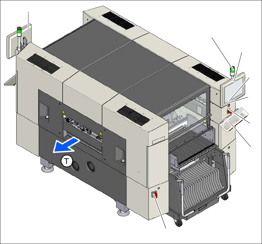
Fig. 5.2 - 1 Controls and displays
5
(1) Main switch (5) Start button
(2) Stop button (black) (6) LCD touchscreen
(3) EMERGENCY STOP button (7) Indicator lamps with horn
(4) Keyboard (T) Direction of PCB transport
(1)
(4)
(3)
(2)
(6)
(7)
(7)
(5)

5 Working with the machine User manual SIPLACE SX1/SX2
5.2 Controls and displays From software version SC 706.1 SP1 Version 10/2014
228
5.2.2 Controls on the machine's operator panels
All the controls can be reached by a 1.40 m tall person. There is a monitor and a keyboard on both
sides of the machine.
The start and stop buttons are located beneath the keyboard. The on-screen dialog will occasion-
ally prompt you to activate certain actions using buttons, and this arrangement will make it easier
for you both to activate and to interactively control these actions.
Main switch 5
The main power switch is used to switch the power supply to the machine on and off. The main
power switch is part of the power module. It is located here because it is only needed for servicing
and preventive maintenance work and is therefore not subject to frequent use.
5
Stop button 5
This button is used to stop the machine.
Start button 5
This button starts the machine after it has been switched on or after faults have been eliminated.
EMERGENCY STOP button 5
The EMERGENCY STOP button latches in the ON position when pressed. The power supply to
the gantry axes, the component trolleys, conveyors and used tape cutters is interrupted and the
voltage supplied to the star axes of the placement heads is reduced. Turn the button to release it.
LCD touchscreen 5
There is a flat LCD screen with a touch-sensitive surface (touchscreen) on either side of the place-
ment machine.
DANGER
Lethal voltages!
Some parts inside the machine carry potentially lethal voltages - even when switched off
at the main power switch.