00196962-04-BA-SX12-V2-EN.pdf - 第79页
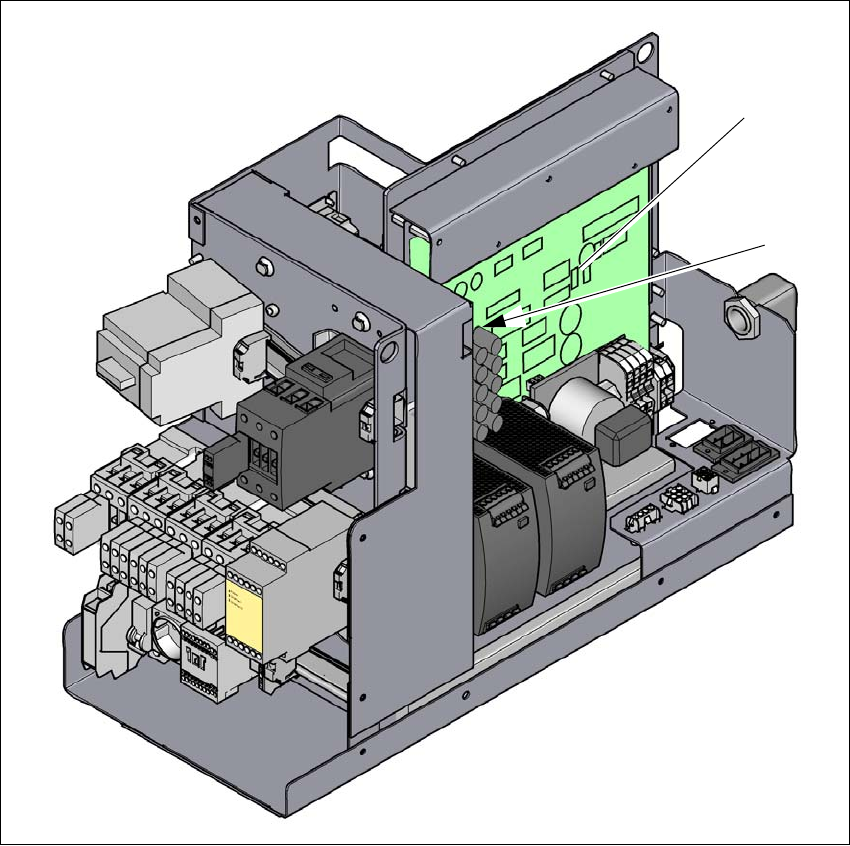
User manual SIPLACE SX1/SX2 2 Operational safety From software version SC 706.1 SP1 Version 10/2014 2.8 Residual voltages and dischar ge times in the machine 79 Fig. 2.8 - 2 Measuring point s on the power supply unit (1)…
2 Operational safety User manual SIPLACE SX1/SX2
2.8 Residual voltages and discharge times in the machine From software version SC 706.1 SP1 Version 10/2014
78
2.8 Residual voltages and discharge times in the machine
If the EMERGENCY STOP button is pressed or the machine is switched off, the 260 VDC link volt-
age for the gantry axes and the 150 VDC link voltage for the star axes are reduced to harmless
residual voltages in a very short time.
2
2
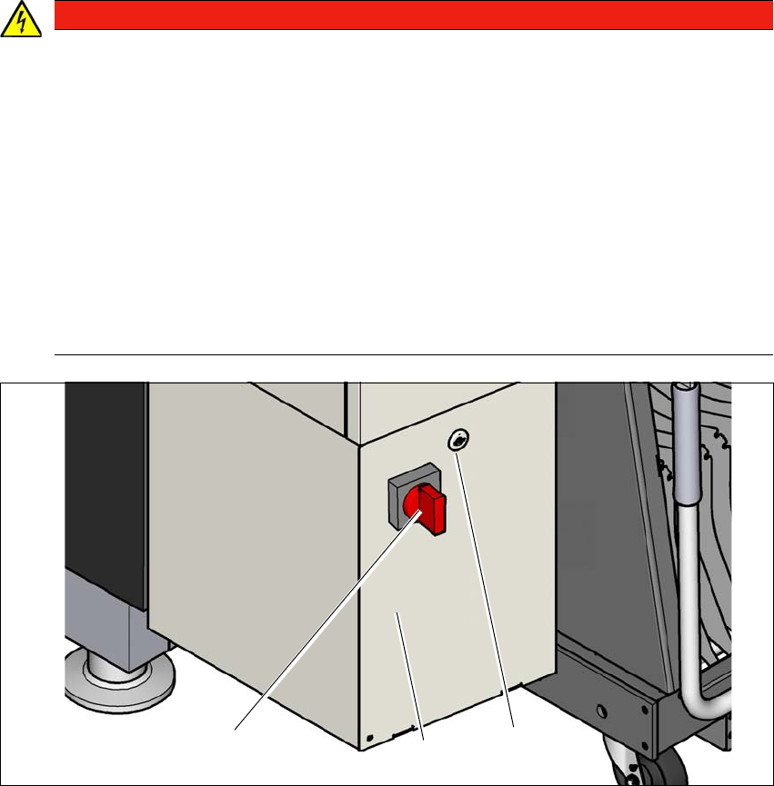
Fig. 2.8 - 1 power supply unit
(1) Main switch
(2) Power supply unit behind the cover
(3) Padlock with bolt in the cover
DANGER
Dangerous voltage levels!
The machine is supplied with 3 x 200 V~, 3 x 208 V~, 3 x 220 V~, 3 x 230 V~, 3 x 380 V~,
3 x 400 V~ or 3 x 415 V~ ± 5 %, 50/60 Hz mains voltage. This means that some parts of
the system carry potentially lethal voltages - even when switched off at the main power
switch.
Incorrect handling of this machine can therefore result in death or severe injury or consid-
erable damage to equipment.
Always follow the applicable accident prevention and DIN regulations (particularly EN
60204, part 1 or IEC 60204, part 1) and the applicable regulations in your own coun-
try.
The covers over the power supply unit may ONLY be opened by appropriately qual-
ified and trained personnel.
(3)
(1)
(2)
User manual SIPLACE SX1/SX2 2 Operational safety
From software version SC 706.1 SP1 Version 10/2014 2.8 Residual voltages and discharge times in the machine
79
Fig. 2.8 - 2 Measuring points on the power supply unit
(1) Fuse and distributor board (A3)
(2) Rectifier board (A7)
(1)
(2)

2 Operational safety User manual SIPLACE SX1/SX2
2.8 Residual voltages and discharge times in the machine From software version SC 706.1 SP1 Version 10/2014
80
2.8.1 Residual voltages and discharge times after switching off the main switch
2
2.8.2 Residual voltages and discharge times after pressing the EMERGENCY
STOP button
2
Measurement point on the
fuse and distributor board
(A3)
(terminal/pin)
Voltage in
normal mode
Residual voltage if
main switch OFF or
power failure
Discharge
times
XB8a / XB8b; Pin 1 in each case 150 V- < 10 VDC < 2s
X25, Pin 1 42 V- < 10 VDC < 2s
X1A / X1B, Pin1 in each case 24 V- < 10 VDC < 2s
XB4; Pin 6 24 V- < 10 VDC < 2s
Measurement point on the
rectifier board (A7
(terminal/pin)
Voltage in
normal mode
Residual voltage if
main switch OFF or
power failure
Discharge
times
XB7a/XB7b, Pin1 in each case 260 V- < 10 VDC < 2s
At the marked point on the rec-
tifier DC40V-S 42 V- < 10 VDC < 2s
Measurement point on the
fuse and distributor board
(A3)
(terminal/pin)
Voltage in
normal mode
Residual voltage after
EMERGENCY STOP
Discharge
times
XB8a / XB8b; Pin 1 in each case 150 V- < 10 VDC < 2s
XB4; Pin 6 24 V- < 10 VDC < 2s
Measurement point on the
rectifier board (A7
(terminal/pin)
Voltage in
normal mode
Residual voltage after
EMERGENCY STOP
Discharge
times
XB7a/XB7b, Pin1 in each case 260 V- < 10 VDC < 2s
At the marked point on the rec-
tifier DC40V-S 42 V- < 10 VDC < 2s