00196962-04-BA-SX12-V2-EN.pdf - 第68页
2 Operational safety User manual SIPLACE SX1/SX2 2.7 Safety features From software version SC 706.1 SP1 Version 10/2014 68 2 Fig. 2.7 - 4 Position of switches and buttons - View of the PCB input side (1) EMERGENCY STOP b…
User manual SIPLACE SX1/SX2 2 Operational safety
From software version SC 706.1 SP1 Version 10/2014 2.7 Safety features
67
2.7.2 Switches and buttons on the machine
2.7.2.1 Position of switches and buttons on the machine
2
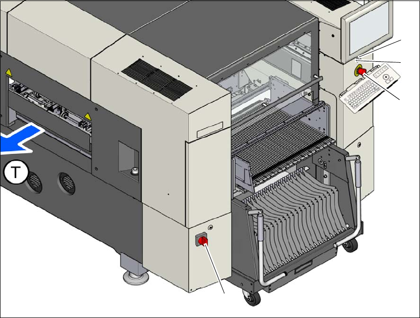
Fig. 2.7 - 3 Position of switches and buttons - View of the PCB output side
(1) Main switch
(2) Start button
(3) EMERGENCY STOP button
(4) Stop button (black)
(T) PCB transport direction
(2)
(1)
(3)
(4)
2 Operational safety User manual SIPLACE SX1/SX2
2.7 Safety features From software version SC 706.1 SP1 Version 10/2014
68
2
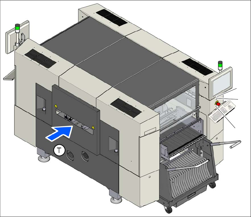
Fig. 2.7 - 4 Position of switches and buttons - View of the PCB input side
(1) EMERGENCY STOP button
(2) Start button
(3) Stop button (black)
(T) PCB transport direction
(3)
(1)
(2)
User manual SIPLACE SX1/SX2 2 Operational safety
From software version SC 706.1 SP1 Version 10/2014 2.7 Safety features
69
2.7.2.2 Position of protective switches on the machine
2
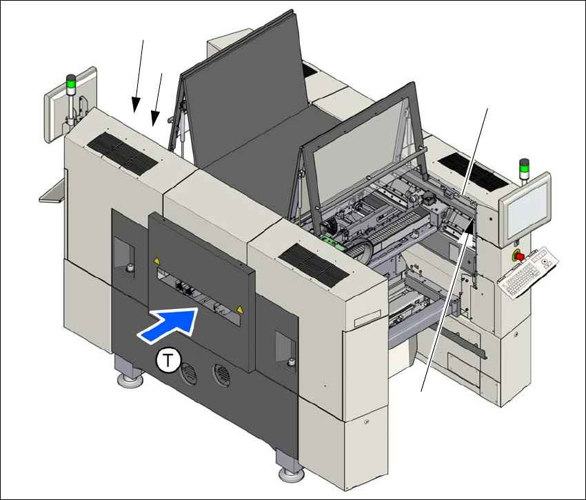
Fig. 2.7 - 5 Position of protective switches on the machine
(1) Protective cover switch, location 1
(2) Protective cover switch, location 2
(3) Protective switch for bumper detection
(T) PCB transport direction
(2)
(1)
(3)
(3)