QP132三级参考手册.pdf.pdf - 第128页
1 1.1 P AM Note: The machine needs to warm up before performing PAM. Run the machine in Production or idle modes for more than 3 hours if possible. Idle program: QP1_IDLE_DIRECT1 Product mode: IDLE-2 It is possible to id…

Chapter 11
PAM

11.1 PAM
Note: The machine needs to warm up before performing PAM. Run the machine in Production
or idle modes for more than 3 hours if possible.
Idle program: QP1_IDLE_DIRECT1
Product mode: IDLE-2
It is possible to idle the machine without removing the PFUs. Ensure there are no feeders
at the pick-up locations.
11.1.1 Nozzle A, B, C and D
1. Enter zero for Center Offset in Proper data. Transmit to the machine and
re-boot.
MQ3ACOAX [PM1]Center Offset A_X
MQ3ACOAY [PM1]Center Offset A_Y
MQ3ACOBX [PM1]Center Offset B_X
MQ3ACOBY [PM1]Center Offset B_Y
MQ3ACOCX [PM1]Center Offset C_X
MQ3ACOCY [PM1]Center Offset C_Y
MQ3ACODX [PM1]Center Offset D_X
MQ3ACODY [PM1]Center Offset D_Y
MQ3ACOEX [PM1]Center Offset E_X
MQ3ACOEY [PM1]Center Offset E_Y
MQ3ACOFX [PM1]Center Offset F_X
MQ3ACOFY [PM1]Center Offset F_Y
2. Use the following programs.
QP1_PAM_YOKO_ALL.PGO
PAM_ALL.PGO
3. Enter zero for Heat expansion in Proper data (Transmit to the machine
and re-boot).
MQ3TEC or MQ3TMCHK Thermal Expansion Compensation = 0
(OFF)
4. Attach 1.3 diameter nozzles to holders, A, B, C and D.
5. Set PAM parts to the feeders.
* Double paper feeder with 4 mm pitch
* Set PAM parts to the left and right. Load feeders to PFU slots 3
and 5.
* Load 2 feeders for each PM. (Prepare 32 of them.)
* Clamp the PFU to the machine.
6. Adjust the IN and OUT manipulators and conveyor width.
Chapter 11 11.1 PAM
Edition 1.1 11-1 QP-132 Level 3 Tutorial
7. Attach double sided tape to the board.
PCB PAM BOARD-1 (white face color)
Set the end of the tape approximately 17.0 mm from the right edge
of the board. Apply to the end in the Y-direction.
8. Press [SET] → [PROPER] → [MAIN UNIT] → [MARK CAMERA] →
[RSLTION/CNTR] to display the image.
9. Align the crosshairs of the real image with the T-mark positioned
between the SS-rail and return conveyor.
10. Press [SET] → [PROPER] → ID code → [MAIN] → [MARK CAMERA] →
[T MARK] → [MEASURE] → START.
11. Repeat a few times to stabilize the value.
12. Attach a 1.3 diameter nozzle to holders A, B, C and D.
13. Press [PROGRAM] → [CHANGE] → Select program PORP_8 to the
foreground.
14. Press [AUTO] to transmit the program to the PMC.
15. Press [SET] → [PROPER] → ID No. → [PM] → select the module →
[FINISH] → [Part Camera] → [CALIB CNTR] → [In turn meas] →
[EXECUTE] → Enter a starting PM No. and final PM No. → START.
16. Attach a 1.3 diameter nozzle to holders E (A) and F (D).
17. Press [PROGRAM] → [CHANGE] → Select program to PORP_17 to the
foreground.
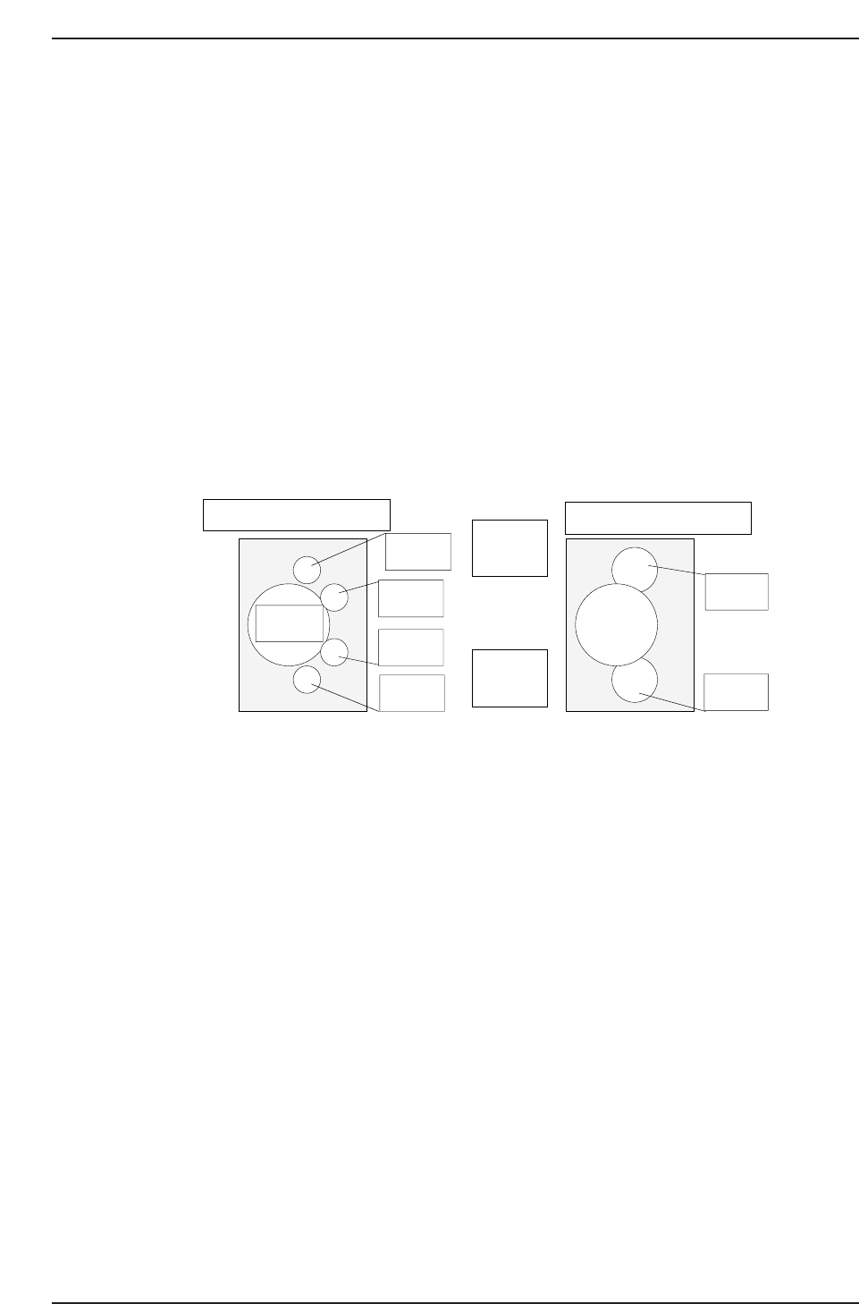
↑
QP132T11001
View from top of X-axis head
Nozzle A
Nozzle B
Nozzle C
Nozzle D
Nozzle E
Nozzle F
(M/C rear)
↓
(M/C front)
View from top of X-axis head
Q gear
Chapter 11 11.1 PAM
Edition 1.1 11-2 QP-132 Level 3 Tutorial