QP132三级参考手册.pdf.pdf - 第60页
• After X No. 13 Max stroke (Between mechanical stoppers): 139 mm Zero set sensor position: 20 mm (2000 pulses) from the minus mechanical stopper. Zero set complete position: 5 mm (500 pulses) from the minus mechanical s…
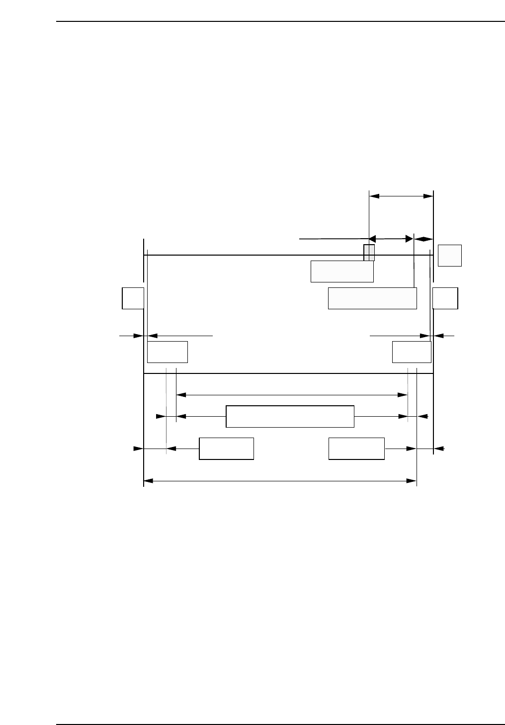
4.2 Replacing X-Axis Motor
This applies to machine X No. 4 to 12.
The mechanical stroke in the X-direction is different for No’s. 4 ~ 12 and 13 and
later.
Max. stroke (Between mechanical stoppers) : 137 mm
Max placing range : 127.5 mm
Resolution : 0.010 mm/pulse
Pulses per rotation : 2000 pulses
X_reduce (deceleration distance) : 500 pulses
Zero set sensor position: 15 mm (1500 pulses) from the minus mechanical
stopper.
Zero set complete position: 5 mm (500 pulses) from the minus mechanical
stopper.
QP132T4003
-MS
0.5 mm 0.5 mm
Soft limit Soft limit
10 mm
(1000 pulses)
20 mm (-2000 pulses)
+MS
Motor
Zero set sensor
Zero set complete pos.
5 mm
(500 pulses)
3.011 mm
6 mm 6 mm
137 mm (Max. stroke)
Nozzle offset Nozzle offset
Mark reading + VP compensation
127.5 mm (Max. placement range)
2.489 mm
Chapter 4 4.2 Replacing X-Axis Motor
Edition 1.1 4-3 QP-132 Level 3 Tutorial
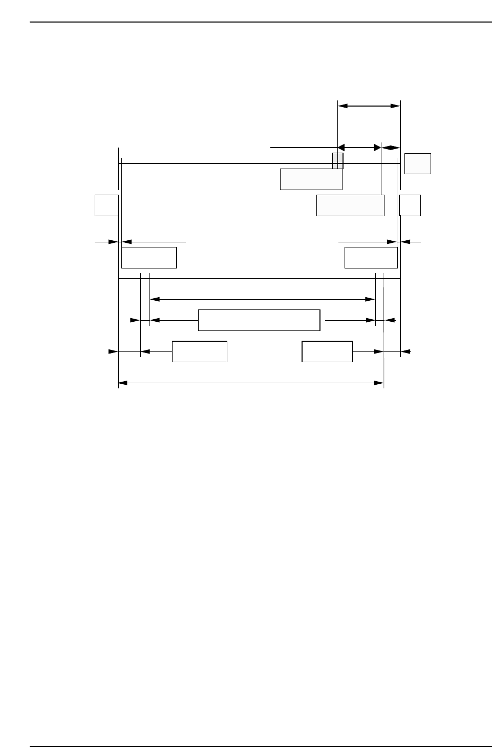
• After X No. 13
Max stroke (Between mechanical stoppers): 139 mm
Zero set sensor position: 20 mm (2000 pulses) from the minus mechanical
stopper.
Zero set complete position: 5 mm (500 pulses) from the minus mechanical
stopper.
10 mm
(1000 pulses)
20 mm (2000 pulses)
5 mm
(500 pulses)
Motor
-MS
0.5 mm 0.5 mm
Software limit Software limit
Zero set sensor
Zero set complete
+MS
127.5 mm (Max. placement range)
2.827 mm
6 mm6 mm
Nozzle offset Nozzle offset
3.373 mm
Mark read + VP compensation
139 mm (Max. stroke)
QP132T4004
Chapter 4 4.2 Replacing X-Axis Motor
Edition 1.1 4-4 QP-132 Level 3 Tutorial

1. Select the PMC. Refer to 4.1 “Setting Proper Data to Select PM” of this
chapter to select PM.
2. Replace the motor and ensure that the belt tension is applied.
3. Move the zero set dog to the right end of the oval-shaped hole so the
zero set sensor turns ON away from the mechanical stopper.
4. [SET] → [MANUAL] → [ETC] → [PM] → [PM MAINTENANCE] →
[ZERO SET] → START.
5. After the completion of zero set, turn OFF the 200V and remove the X-
axis timing belt.
6. Push the XY-robot against the plus side mechanical stopper (motor side).
7. Rotate the X-axis motor to servo counter 500 ± 100 pulses and reattach
the timing belt.
8. Adjust the belt tension of the X-axis pulley at 0, 90, 180 and 270 degrees.
Min.: more than 174 Hz
Max.: less than 274 Hz.
9. Push the XY-robot against the mechanical stopper and confirm that servo
counter value is within tolerance.
10. Move the XY-robot to -1500 ± 100 pulses and adjust the X-axis zero set
dog.
11. Move the XY-robot and confirm that X-axis zero set sensor turns on at
-1500 ± 100 pulses.
Chapter 4 4.2 Replacing X-Axis Motor
Edition 1.1 4-5 QP-132 Level 3 Tutorial