QP132三级参考手册.pdf.pdf - 第45页
2.2.4 PCB Arrival Check and Reduction Sensors 1. Adjust the arrival check sensor to the position where the gap between right surface of the sensor and stopper is 0.5 mm. 2. Adjust the reduction sensor to the position whe…
7. Press [SET] → [PROPER] → [MAIN UNIT] → [ETC.] → [MANIPULATE]
→ [AXIS CHG P0/(AXIS CHG MX9)] → [PK DIRECT PO] → [SET] to
record the value in Proper data.
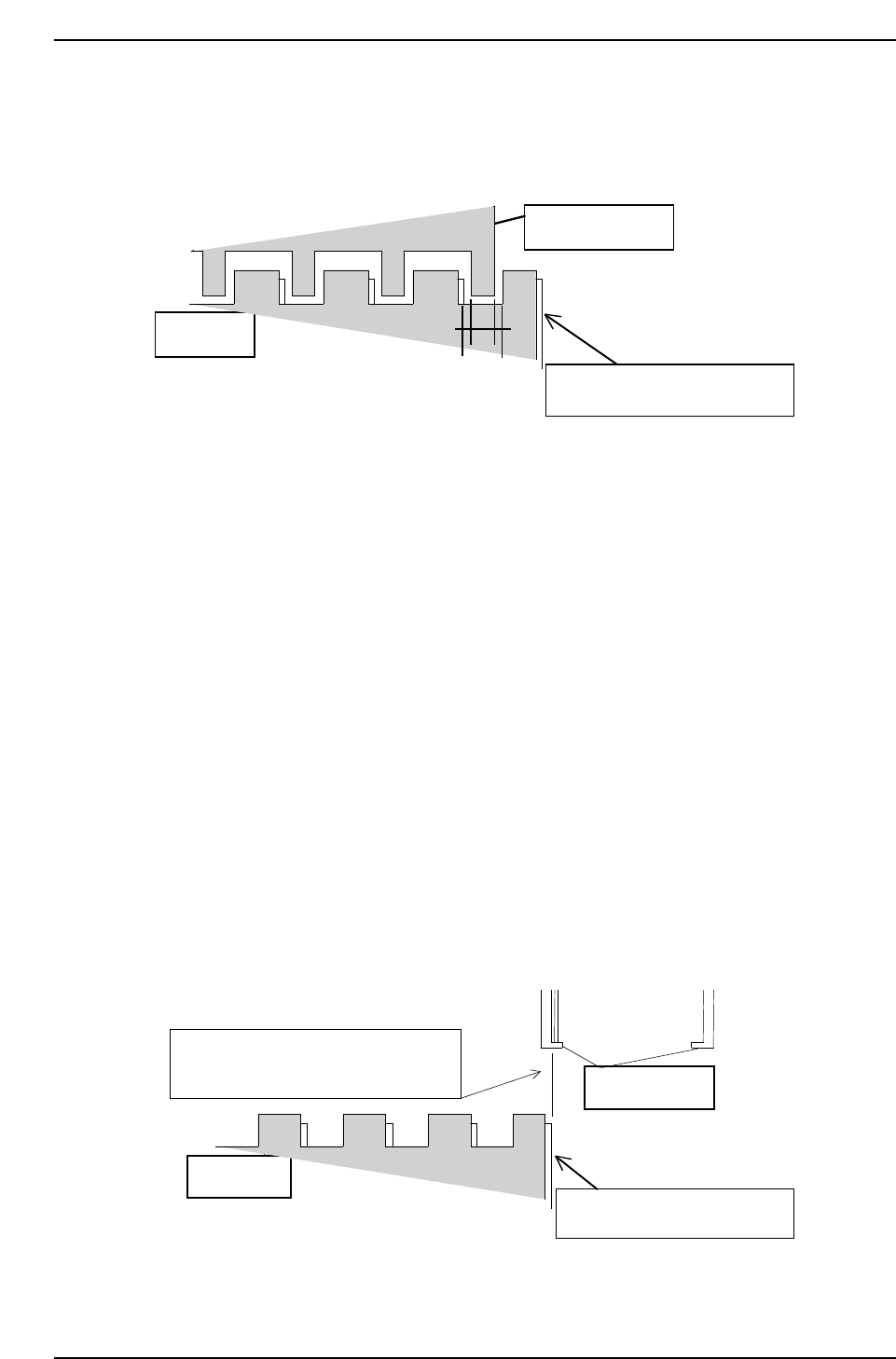
2.2.3 PCB Pickup Position PO (Rotate-Loading)
1. Press the EMERGENCY STOP button to shutdown the 200V.
2. On the out-pallet loader, place the pallet at position after shifting 10 mm.
3. Press [SET] → [MANUAL] → [I/O] → [STANDARD I/O] → [OUTPUT]
and Y073 PCB UL HOOK CL to open the hook on the pallet.
4. Move the MX-axis to PCB_Pickup_Position.PO_FWD.
5. Press Y074 UL TURN to turn the manipulator.
6. Adjust the MX-axis so that the inner side of the reference jaw aligns with
the right edge of the 8-inch pallet.
7. Press [SET] → [PROPER] → [MAIN UNIT] → [ETC.] → [MANIPULATE]
→ [LD TURN/(PK PLACE P0)] → [SET] to record the value in Proper
data.
8-inch pallet
Inner side of reference jaw flushes with
the edge of the 8-inch pallet.
Manipulator jaw
Lower plate of the clamping jaw
QP1312T2004
QP132T2003
Manipulator jaw
Lower plate of the clamping jaw
8-inch pallet
Chapter 2
2.2 Measuring Out Manipulator Proper Data and Adjustment
Edition 1.1 2-4 QP-132 Level 3 Tutorial
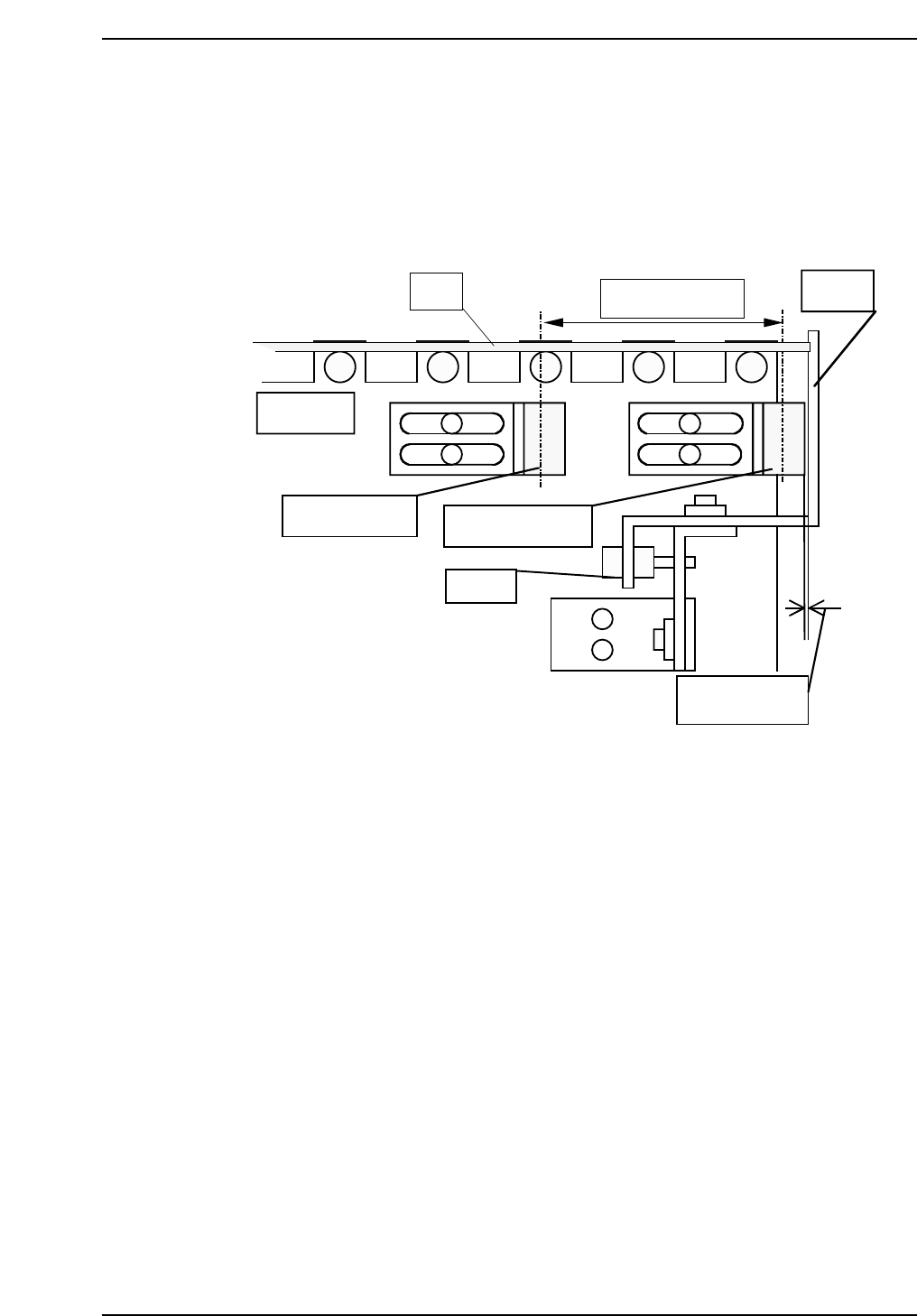
2.2.4 PCB Arrival Check and Reduction Sensors
1. Adjust the arrival check sensor to the position where the gap between
right surface of the sensor and stopper is 0.5 mm.
2. Adjust the reduction sensor to the position where the distance between
the reduction sensor and arrival check sensor is 60 mm.
QP132T2005
PCB
In conveyor
Approx. 60 mm
Stopper
Reduction sensor
Arrival check sensor
Adj. BT
Approx. 0.5 mm
Chapter 2
2.2 Measuring Out Manipulator Proper Data and Adjustment
Edition 1.1 2-5 QP-132 Level 3 Tutorial
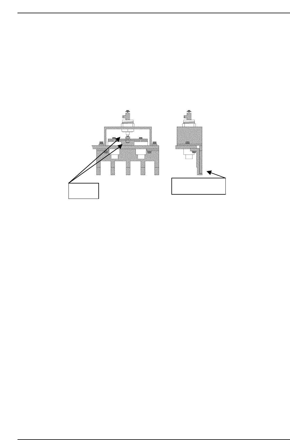
2.2.5 PCB Retaining Cylinder for the Manipulator
1. Press [SET] → [MANUAL] → [I/O] → [STANDARD I/O] → [OUTPUT]
and use Y050 PCBCD UP to raise the manipulator.
2. Loosen the two (2) black nuts attached to the cylinder.
3. Rotate the nuts, and move the jaw upwards. Then, lower the jaw to a
position where a 0.5 mm feeler gauge can fit in.
4. Remove the feeler gauge and slightly lower the jaw. Then lock it.
5. Ensure that the feeler gauge cannot fit in.
6. Clamp the 0.8 mm feeler gauge, and ensure that it clamps properly.
Adj. nuts
Plate feeler gauge.
QP132T2006
Chapter 2
2.2 Measuring Out Manipulator Proper Data and Adjustment
Edition 1.1 2-6 QP-132 Level 3 Tutorial