QP132三级参考手册.pdf.pdf - 第84页
6.2.2 Camera Center 1. Press [SET] → [PROPER] → ID No. → [PM] → select the module → [FINISH] → [Part Camera] → [Crosshair display] to display an image. 2. Attach a 1.3 diameter nozzle to holder A, B, C and D. 3. Use the …
6.2 Measuring Parts Camera Proper Data and
Adjustment
6.2.1 Delta and Parts Camera Pixel
1. Attach a resolution jig (ACGPJ9060) to holder A.
2. Set a dial indicator on the side of jig.
3. Move the X-axis using the inching keys. Rotate Q and the placing head
and position the side of jig to parallel to the X-axis.
Tolerance : 0.01 mm
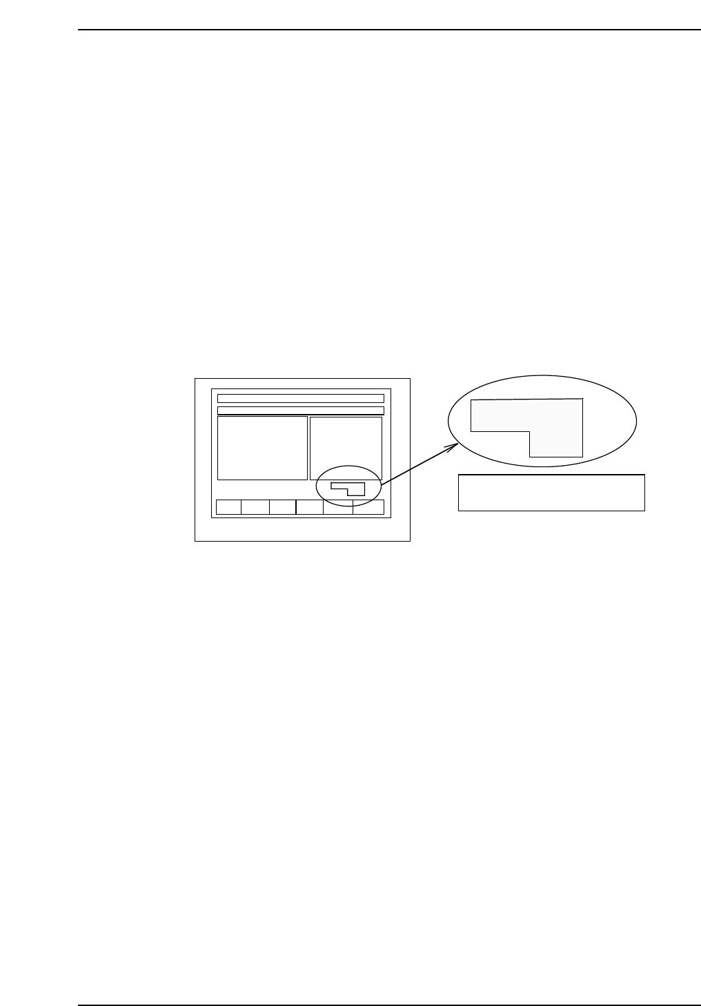
Note: When using the inching keys, check the desired PM. Check the jog display at the bottom
right of the monitor.
4. Press [SET] → [PROPER] → ID No. → [PM] → select the module to be
focused → [FINISH] → [Part Camera] → [Crosshair display] to display
the image.
5. Move the resolution jig to the center of the camera using the inching
keys.
6. Press [SET] → [PROPER] → Enter ID No. → [PM] → select the module →
[Part Camera] → [Resolution] → START.
Delta X: ± 50.0 um
Delta Y: ± 50.0 um
Delta Q: less than ± 0.050 deg.
X: 24.500 ± 0.5 um
Y: 24.500 ± 0.5 um
7. Adjust the camera height and angle.
8. Re-tighten and check the resolution several times.
F1 F2 F3 F4 F5 F6
jog X Y θ
PM01
Check the axis to be jogged and
PM no. in this display.
QP132T6002
Chapter 6
6.2 Measuring Parts Camera Proper Data and Adjustment
Edition 1.1 6-3 QP-132 Level 3 Tutorial
6.2.2 Camera Center
1. Press [SET] → [PROPER] → ID No. → [PM] → select the module →
[FINISH] → [Part Camera] → [Crosshair display] to display an image.
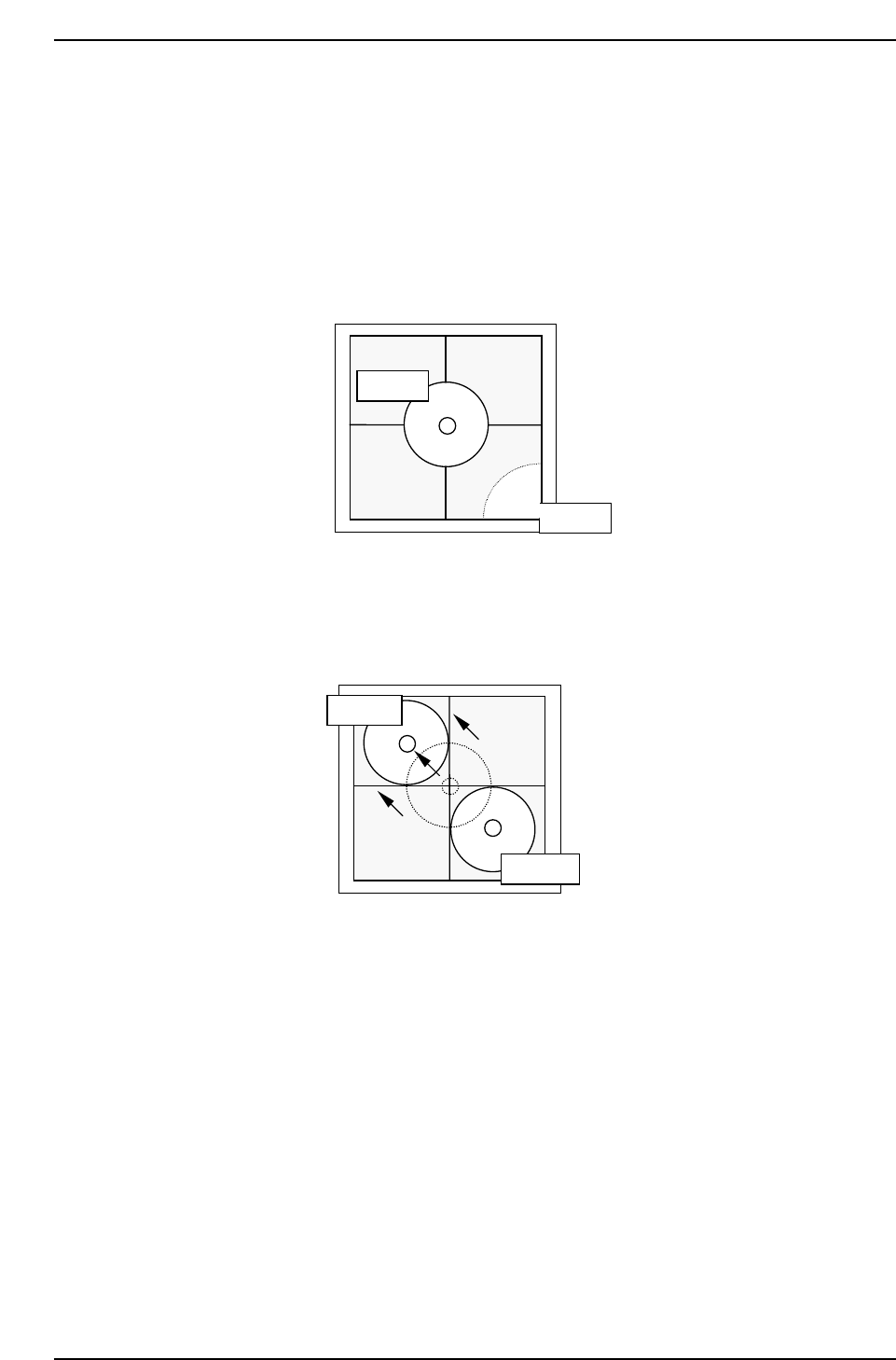
2. Attach a 1.3 diameter nozzle to holder A, B, C and D.
3. Use the inching keys to move reference nozzle A to the camera center.
4. Press [Part Camera] → [Camera Center] → Select the nozzle AB →
[EXECUTE]. The nozzle will move between nozzle A and B to auto-
calibrate.
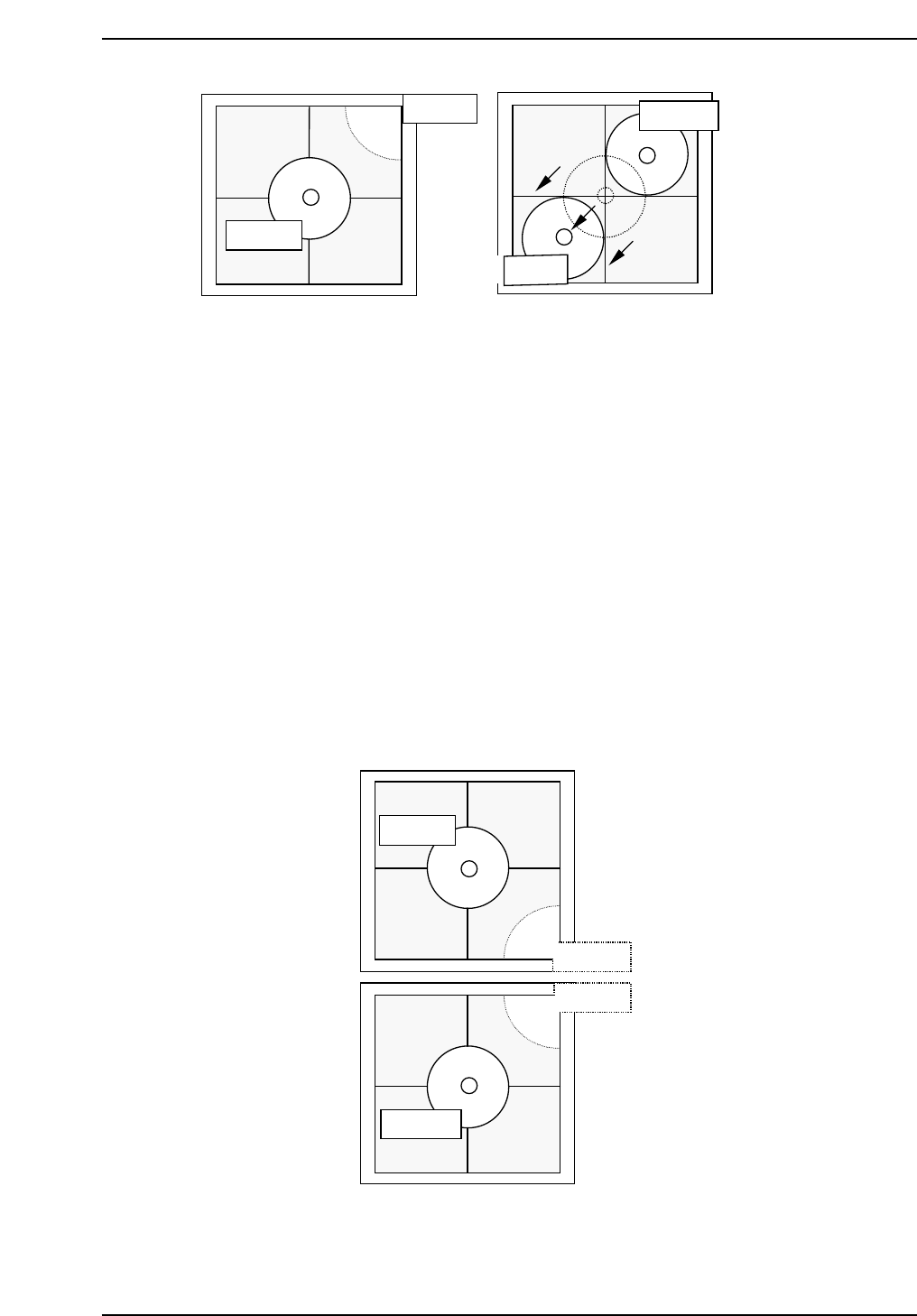
5. Use the inching keys to move reference nozzle D to the camera center.
6. Press [Part Camera] → [Camera Center] → Select the nozzle CD →
[EXECUTE]. The nozzle will move between nozzle C and D to auto-
calibrate.
QP132T6004
Nozzle A
Nozzle B
QP132T6003
Nozzle A
Nozzle B
Chapter 6
6.2 Measuring Parts Camera Proper Data and Adjustment
Edition 1.1 6-4 QP-132 Level 3 Tutorial
Note: It is possible to attach 8.0 mm backlight disks to holders A, B, C and D when using small
nozzles. As for larger disks, (17.0 backlight disks), they should be attached to holders A
and D and are referred to as nozzles E and F. Therefore, nozzles A and E, D and F use
the same holders. Separate Proper data measurement if necessary.
7. Press [SET] → [PROPER] → ID No. → [PM] → select the module →
[FINISH] → [Part Camera] → [Crosshair display] to display a real image
of the nozzle on the monitor.
8. Attach a 1.3 diameter nozzle to holder E (A) and F (D).
9. Use the inching keys to move reference nozzle E to the camera center
10. Press [Part Camera] → [Camera Center] → Select the nozzle E → [SET].
11. Press [Part Camera] → [Camera Center] → Select the nozzle F → [SET].
QP132T6006
Nozzle E
Nozzle B
Nozzle C
Nozzle F
QP132T6005
Nozzle C
Nozzle C
Nozzle D
Nozzle D
Chapter 6
6.2 Measuring Parts Camera Proper Data and Adjustment
Edition 1.1 6-5 QP-132 Level 3 Tutorial