QP132三级参考手册.pdf.pdf - 第89页
6.2.7 Lighting Note: VP version : V2.96 or after 1. Attach 0.7 diameter nozzles to all holders. 2. Select program PRODUCT_1005_QP1_D. 3. Press [SET] → [MANUAL] → [NOZZLE] → [NOZZLE COND] → [In turn meas] or [Simult meas]…
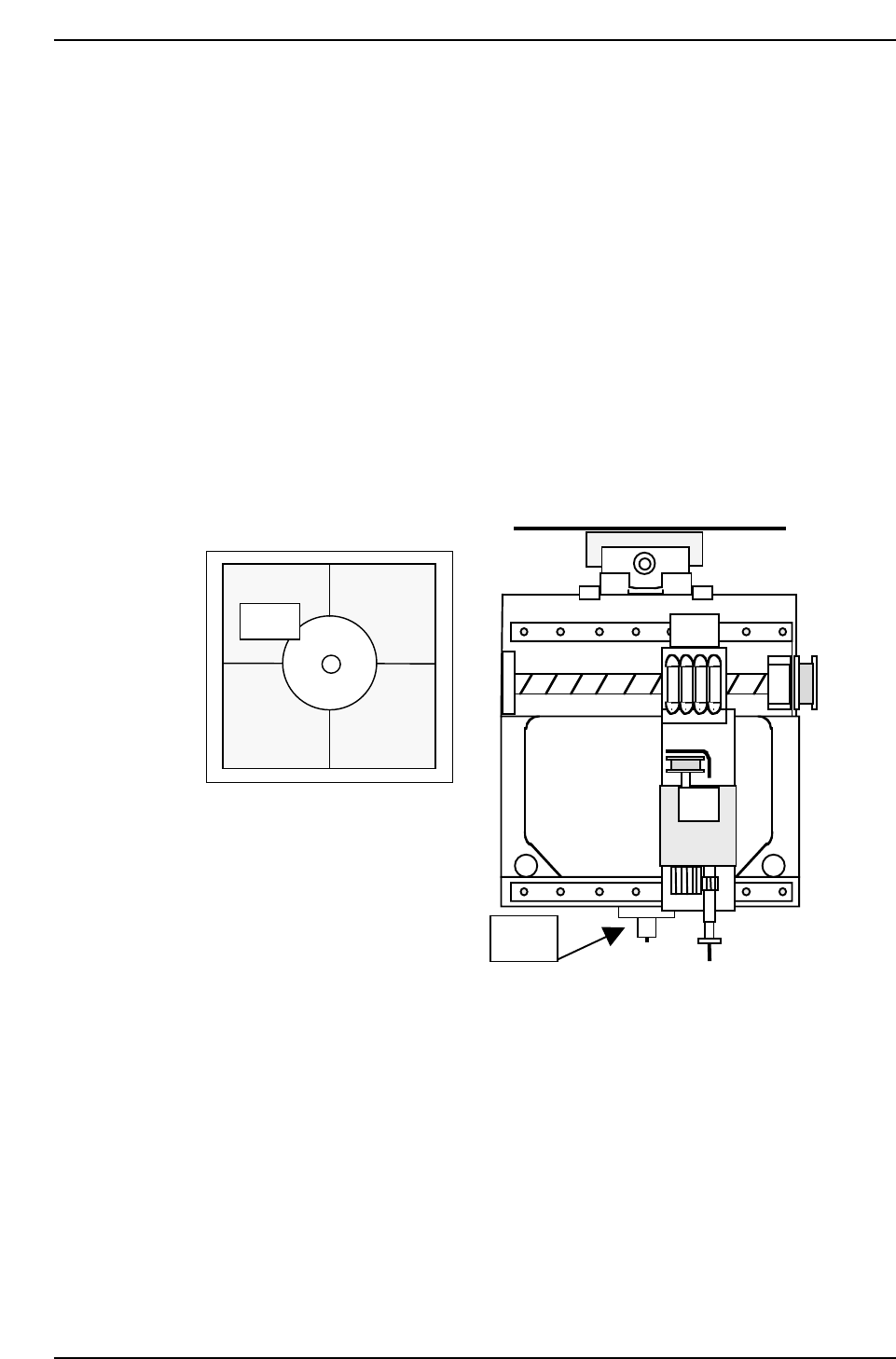
6.2.6 T Mark Reference on Y Direction and Mark
Reference Value X
Note: Measuring the positions of the Heat Expansion jig attached to each head.
1. Press [SET] → [MANUAL] → [VISION] → [ADJUST] → [GET ACQ] →
[DISPLAY] to acquire a real image of the Parts camera on the monitor.
2. Turn OFF the 200V.
3. Move the head so that the jig appears at the center of the crosshairs.
4. Press [SET] → [PROPER] → ID No. → [PM] → select the module →
[FINISH] → [Part Camera] → [T-Mark] → [EXECUTE] to activate auto-
calibration.
Jig
Jig
QP132T6008
Chapter 6
6.2 Measuring Parts Camera Proper Data and Adjustment
Edition 1.1 6-8 QP-132 Level 3 Tutorial

6.2.7 Lighting
Note: VP version : V2.96 or after
1. Attach 0.7 diameter nozzles to all holders.
2. Select program PRODUCT_1005_QP1_D.
3. Press [SET] → [MANUAL] → [NOZZLE] → [NOZZLE COND] → [In
turn meas] or [Simult meas] → [EXECUTE] → Enter Starting PM No. and
the Last PM No. → START.
4. Press [RESULTS] → [B_LIGHT DATA] to check the brightness.
Gray scale value : 170 ± 20
5. If the gray scale value is out of range, perform the following in order:
* Replace the nozzles.
* Replace the UV lamp.
* Replace the camera.
Chapter 6
6.2 Measuring Parts Camera Proper Data and Adjustment
Edition 1.1 6-9 QP-132 Level 3 Tutorial

Notes:
Chapter 6
6.2 Measuring Parts Camera Proper Data and Adjustment
Edition 1.1 6-10 QP-132 Level 3 Tutorial