QP132三级参考手册.pdf.pdf - 第43页
2.2 Measuring Out Manipulator Proper Data and Adjustment 2.2.1 PCB Placing Position PO 1. Press the EMERGENCY STOP button to shutdown the 200V. 2. Move the PO-axis to the out-conveyor. 3. Adjust the speed controller so t…

9. After completion of zero-setting, press the EMERGENCY STOP button
to turn OFF the 200V.
10. Loosen the coupling and push the PO-robot against the minus side
mechanical stopper.
11. Rotate the motor to set the counter value to -400 ± 40 pulse.
12. Tighten the coupling. Coupling Torque: 1.47 Nm (0.15 kgf/m)
13. Push the PO-robot against the minus side mechanical stopper and make
sure the servo counter value is -400 ± 40 pulse.
14. Rotate the motor to set the servo counter to 400 ± 40 pulse.
15. Adjust the dog position so the zero set sensor turns ON at this position.
16. Press [SERVO ON] → START to Servo ON and zero set.
17. After completion of zero set, press the EMERGENCY STOP button to
turn OFF the 200V.
18. Move the PO-robot to the position where zero set sensor turns on and
make sure the servo counter value is 400 ± 40 pulse.
Chapter 2 2.1 Replacing PO-Axis Motor
Edition 1.1 2-2 QP-132 Level 3 Tutorial

2.2 Measuring Out Manipulator Proper Data
and Adjustment
2.2.1 PCB Placing Position PO
1. Press the EMERGENCY STOP button to shutdown the 200V.
2. Move the PO-axis to the out-conveyor.
3. Adjust the speed controller so that the manipulator descends slowly.
4. Press [SET] → [MANUAL] → [I/O] → [STANDARD I/O] → [OUTPUT]
and Y071 PCB UL DOWN.
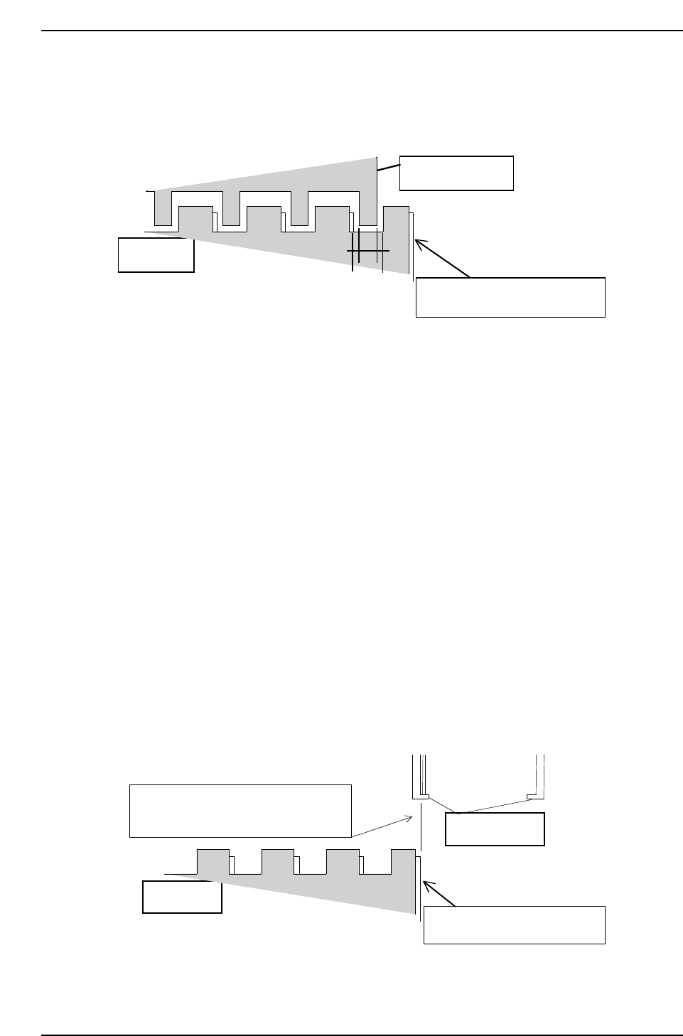
5. Move the PO-axis to the position where the second from the right jaw
aligns evenly within the right end cutout on the IN conveyor. Refer to
the illustration below.
6. Press [SET] → [PROPER] → [MIAIN UNIT] → [ETC] → [MANIPULATE]
→ [PLACE PO] → [SET] to record the value in Proper data.
2.2.2 PCB Pickup Position PO FWD
1. Press the EMERGENCY STOP button to shutdown the 200V.
2. Move the MX-axis to the pallet.
3. On the out-pallet loader, place an 8 inch pallet at position after shifting
10 mm.
4. Adjust the speed controller so that the manipulator descends slowly.
5. Press [SET] → [MANUAL] → [I/O] → [STANDARD I/O] → [OUTPUT]
and Y071 PCB UL DOWN.
6. Adjust the PO-axis so that the reference jaw of the manipulator is at the
center of the right end cut-out of the OUT conveyor.
Manipulator jaw
Out conveyor
QP132T2002
Chapter 2
2.2 Measuring Out Manipulator Proper Data and Adjustment
Edition 1.1 2-3 QP-132 Level 3 Tutorial
7. Press [SET] → [PROPER] → [MAIN UNIT] → [ETC.] → [MANIPULATE]
→ [AXIS CHG P0/(AXIS CHG MX9)] → [PK DIRECT PO] → [SET] to
record the value in Proper data.
2.2.3 PCB Pickup Position PO (Rotate-Loading)
1. Press the EMERGENCY STOP button to shutdown the 200V.
2. On the out-pallet loader, place the pallet at position after shifting 10 mm.
3. Press [SET] → [MANUAL] → [I/O] → [STANDARD I/O] → [OUTPUT]
and Y073 PCB UL HOOK CL to open the hook on the pallet.
4. Move the MX-axis to PCB_Pickup_Position.PO_FWD.
5. Press Y074 UL TURN to turn the manipulator.
6. Adjust the MX-axis so that the inner side of the reference jaw aligns with
the right edge of the 8-inch pallet.
7. Press [SET] → [PROPER] → [MAIN UNIT] → [ETC.] → [MANIPULATE]
→ [LD TURN/(PK PLACE P0)] → [SET] to record the value in Proper
data.
8-inch pallet
Inner side of reference jaw flushes with
the edge of the 8-inch pallet.
Manipulator jaw
Lower plate of the clamping jaw
QP1312T2004
QP132T2003
Manipulator jaw
Lower plate of the clamping jaw
8-inch pallet
Chapter 2
2.2 Measuring Out Manipulator Proper Data and Adjustment
Edition 1.1 2-4 QP-132 Level 3 Tutorial