QP132三级参考手册.pdf.pdf - 第46页
2.2.5 PCB Retaining Cylinder for the Manipulator 1. Press [SET] → [MANUAL] → [I/O] → [STANDARD I/O] → [OUTPUT] and use Y050 PCBCD UP to raise the manipulator. 2. Loosen the two (2) black nuts attached to the cylinder. 3.…
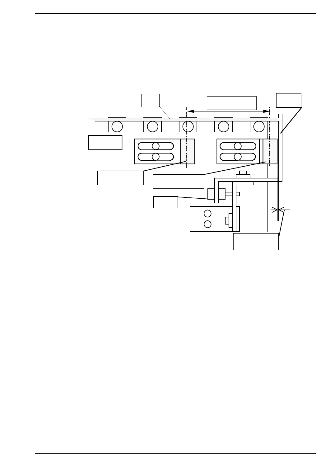
2.2.4 PCB Arrival Check and Reduction Sensors
1. Adjust the arrival check sensor to the position where the gap between
right surface of the sensor and stopper is 0.5 mm.
2. Adjust the reduction sensor to the position where the distance between
the reduction sensor and arrival check sensor is 60 mm.
QP132T2005
PCB
In conveyor
Approx. 60 mm
Stopper
Reduction sensor
Arrival check sensor
Adj. BT
Approx. 0.5 mm
Chapter 2
2.2 Measuring Out Manipulator Proper Data and Adjustment
Edition 1.1 2-5 QP-132 Level 3 Tutorial
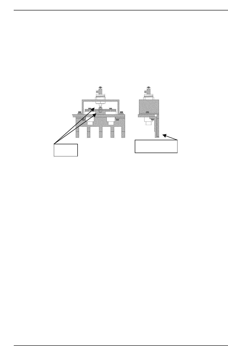
2.2.5 PCB Retaining Cylinder for the Manipulator
1. Press [SET] → [MANUAL] → [I/O] → [STANDARD I/O] → [OUTPUT]
and use Y050 PCBCD UP to raise the manipulator.
2. Loosen the two (2) black nuts attached to the cylinder.
3. Rotate the nuts, and move the jaw upwards. Then, lower the jaw to a
position where a 0.5 mm feeler gauge can fit in.
4. Remove the feeler gauge and slightly lower the jaw. Then lock it.
5. Ensure that the feeler gauge cannot fit in.
6. Clamp the 0.8 mm feeler gauge, and ensure that it clamps properly.
Adj. nuts
Plate feeler gauge.
QP132T2006
Chapter 2
2.2 Measuring Out Manipulator Proper Data and Adjustment
Edition 1.1 2-6 QP-132 Level 3 Tutorial

2.3 Training Evaluation
Circle the most appropriate answer from the list below.
(1) Which is the correct value of PO-axis coupling torque?
a. 1.35 Nm
b. 0.15 kgf/m
c. 1.45 Nm
(2) To measure the PCB Pickup Position PO FWD, adjust the pallet jaw and
manipulator jaw to:
a. align evenly.
b. have 1.4 mm distance.
c. have contact.
(3) The distance between PCB Arrival and Reduction Sensors is:
a. 61 mm.
b. 70 mm.
c. 50 mm.
(4) Which is the correct order of measuring PCB Pickup Position PO FWD
and PCB Pickup Position PO (Rotate-loading)?
a. At the same time
b. PCB Pickup Position PO (Rotate-loading) first
c. PCB Pickup Position PO FWD first
(5) PO-axis zero set sensor is set at:
a. 400 pulses.
b. 140 pulses.
c. 800 pusles.
Chapter 2 2.3 Training Evaluation
Edition 1.0 2-7 QP-132 Level 3 Tutorial