QP132三级参考手册.pdf.pdf - 第35页
16. Press [SET] → [PROPER] → [MAIN UNIT] → [ETC.] → [MANIPULATE] → [LD TURN] → [SET] to record the value in Proper data. 1.3.4 PCB Landing Position MX (Rotate Loading) Note: The following conditions are necessary. * Cent…
1.3.3 PCB Landing Position MX FDW (Straight
Loading)
1. Press the EMERGENCY STOP button to shutdown the 200V.
2. Move the MX-axis to the in-conveyor.
3. In pallet loader, place a pallet to position before shifting 10 mm
4. Press [SET] → [MANUAL] → [I/O] → [STANDARD I/O] → [OUTPUT]
and use Y048 P.IN PLT OPN to open the hook on the pallet.
5. Place a PCB on the IN conveyor against the stopper.
6. Move the MX-axis to PCB_Pickup_Pos_MX.
7. Press Y052 PCB LD HOOK OP to open the hook.
8. Press Y051 PCB LD DOWN to lower the manipulator.
9. Press Y053 PCB LD HOOK CL to clamp the PCB.
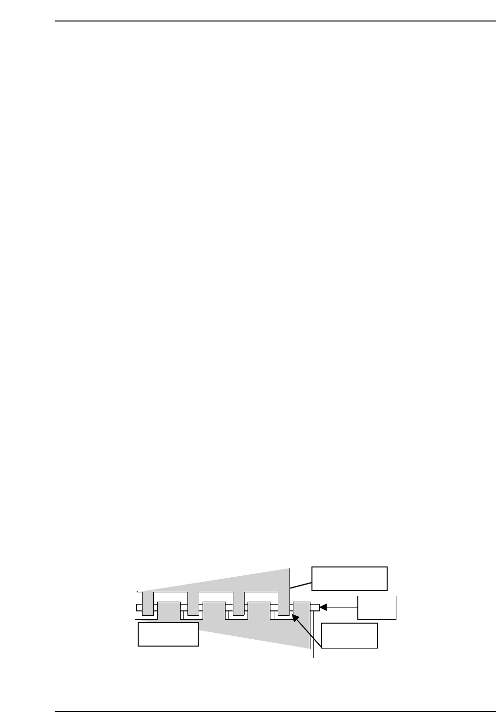
10. Check the clearance between the right edge of the reference jaw on the
manipulator and the right edge of the board is 7.75 mm (± 0.5 mm).
11. Press Y050 PCD LD UP to raise the manipulator.
12. Move the MX-axis to the pallet.
13. Press [SET] → [MANUAL] → [I/O] → [STANDARD I/O] → [OUTPUT]
and use Y051 PCB LD DOWN.
14. Lower the Manipulator down slowly.
15. Adjust the MX-axis so that the clearance between the right edge of the
reference jaw and left edge of the pallet is 1.33 mm.
QP132T1005
8-inch pallet
Manipulator jaw
PCB
1.3 mm
Chapter 1
1.3 Measuring In Manipulator Proper Data and Adjustment
Edition 1.1 1-7 QP-132 Level 3 Tutorial
16. Press [SET] → [PROPER] → [MAIN UNIT] → [ETC.] → [MANIPULATE]
→ [LD TURN] → [SET] to record the value in Proper data.
1.3.4 PCB Landing Position MX (Rotate Loading)
Note: The following conditions are necessary.
* Center of the rotate-position of the IN manipulator is adjusted.
* Height, parallelism and perpendicularity of the IN manipulator are adjusted.
* Height and parallelism of the IN conveyor is adjusted.
* IN_ pallet loader is adjusted.
1. Press the EMERGENCY STOP button to shutdown the 200V.
2. In- pallet loader, place the pallet at the position before shifting 10 mm.
3. Press [SET] → [MANUAL] → [I/O] → [STANDARD I/O] → [OUTPUT]
and Y019 P.IN PLT CLS to close the hook on pallet.
4. Move the MX-axis to PCB_Landing_Pos_MX_FDW.
5. Press Y054 PCB TURN to turn the manipulator.
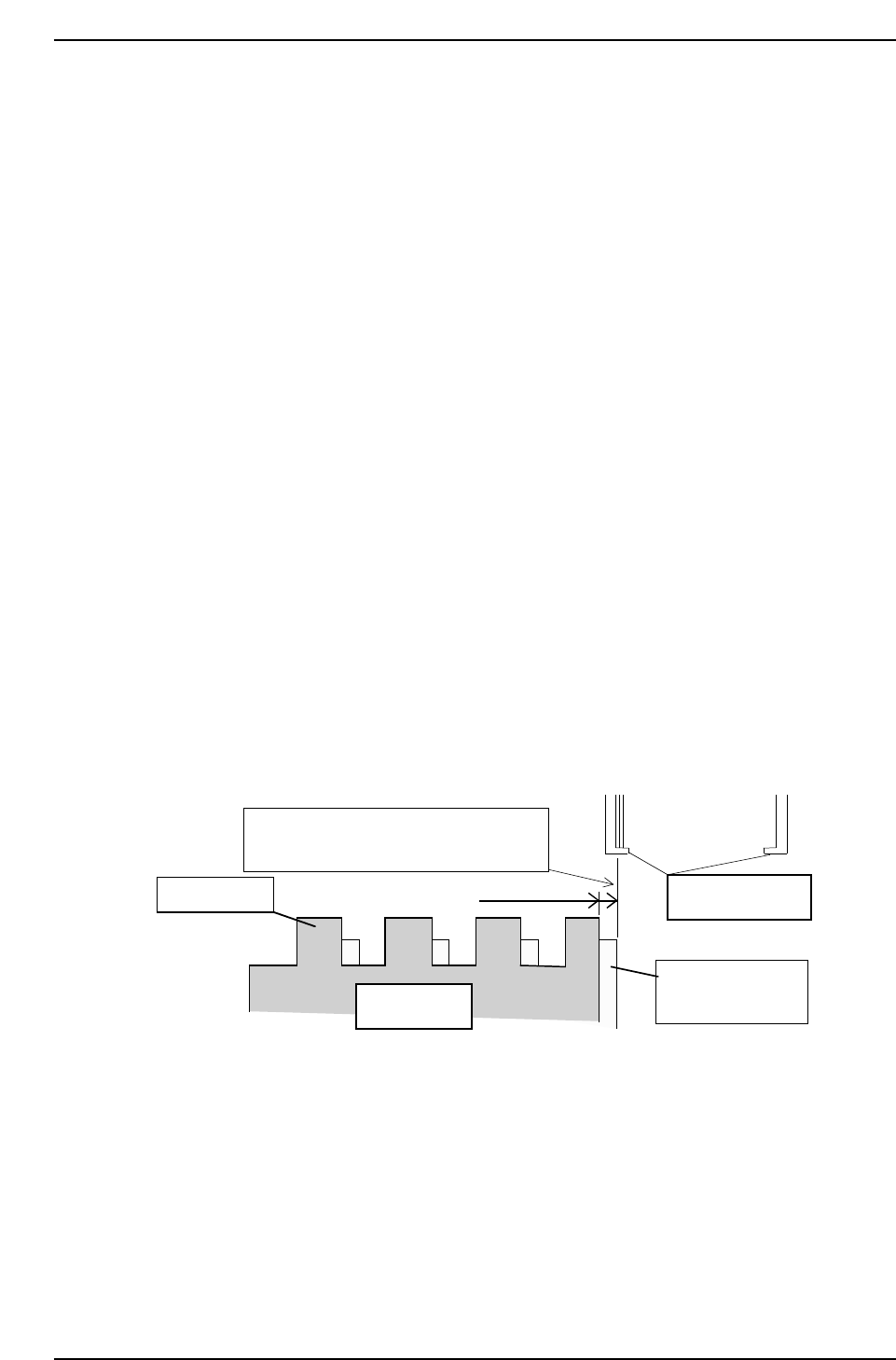
6. Move the MX-axis so that the inside of the reference jaw is aligned with
the right side of the lower plate of the jaw.
Note: The right side lower plate of the clamping jaw and right top of the clamping jaw, right
side of the pallet is 1.455 mm shifted to the right when the pallet is unclamped.
7. Press [SET] → [PROPER] → [MAIN UNIT] → [ETC.] → [MANIPULATE]
→ [LD TURN] → [SET] to record the value in Proper data.
Inner side of reference jaw flushes with
the edge of the 8-inch pallet.
Clamping jaw
8-inch pallet
1.455 mm
Manipulator jaw
Lower plate of the
clamping jaw
QP132T1006
Chapter 1
1.3 Measuring In Manipulator Proper Data and Adjustment
Edition 1.1 1-8 QP-132 Level 3 Tutorial
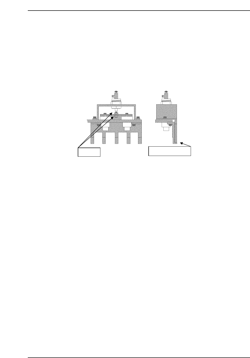
1.3.5 PCB Retaining Cylinder for the Manipulator
1. Press [SET] → [MANUAL] → [I/O] → [STANDARD I/O] → [OUTPUT]
and use Y050 PCBCD UP to raise the manipulator.
2. Loosen the two (2) black nuts attached to the cylinder.
3. Rotate the nuts, and move the jaw upwards. Then, lower the jaw to a
position where a 0.5 mm feeler gauge can fit in.
4. Remove the feeler gauge and slightly lower the jaw. Then lock it.
5. Ensure that the feeler gauge cannot fit in.
6. Clamp the 0.8 mm feeler gauge, and ensure that it clamps properly.
Adj. nuts
Place feeler gauge
QP132T1007
Chapter 1
1.3 Measuring In Manipulator Proper Data and Adjustment
Edition 1.1 1-9 QP-132 Level 3 Tutorial