QP132三级参考手册.pdf.pdf - 第32页
1.3 Measuring In Manipulator Proper Data and Adjustment Note: Proper data measurement should be done with the manipulator jaw closed using an 8 inch pallet. 1.3.1 PCB Pickup Position MX 1. Press the EMERGENCY STOP button…

9. After completion of zero set, press the EMERGENCY STOP button to
turn OFF the 200V.
10. Loosen the coupling and manually push the MY-robot against the minus
side mechanical stopper.
11. Rotate the motor to the value at -2000 [-4000] ± 200 [400] pulse.
12. Tighten the coupling. Coupling Torque: 0.98 Nm (0.1 kgf/m)
13. Push the MY-robot against the minus side mechanical stopper and check
the servo counter value: -2000 [-4000] ± 200 [400] pulse.
14. Move the head to set the servo counter to 1500 [3000] ± 200 [400] pulse.
15. Adjust the dog position so the zero set sensor turns ON at this position.
16. Press [SERVO ON] → START to Servo ON and zero set again.
17. After completion of zero set, press the EMERGENCY STOP button to
turn OFF the 200V.
18. Manually move the MY-robot to the position where the zero set sensor
turns on and make sure the servo counter value is 1500 [3000] ± 200 [400]
pulse.
Chapter 1 1.2 Replacing MY-Axis Motor
Edition 1.1 1-4 QP-132 Level 3 Tutorial
1.3 Measuring In Manipulator Proper Data and
Adjustment
Note: Proper data measurement should be done with the manipulator jaw closed using an 8
inch pallet.
1.3.1 PCB Pickup Position MX
1. Press the EMERGENCY STOP button to shutdown the 200V.
2. Move the MX-axis to the conveyor side.
3. Adjust the speed controller so that the manipulator descends slowly.
4. Press [SET] → [MANUAL] → [I/O] → [STANDARD I/O] → [OUTPUT]
and Y051 PCB LD DOWN.
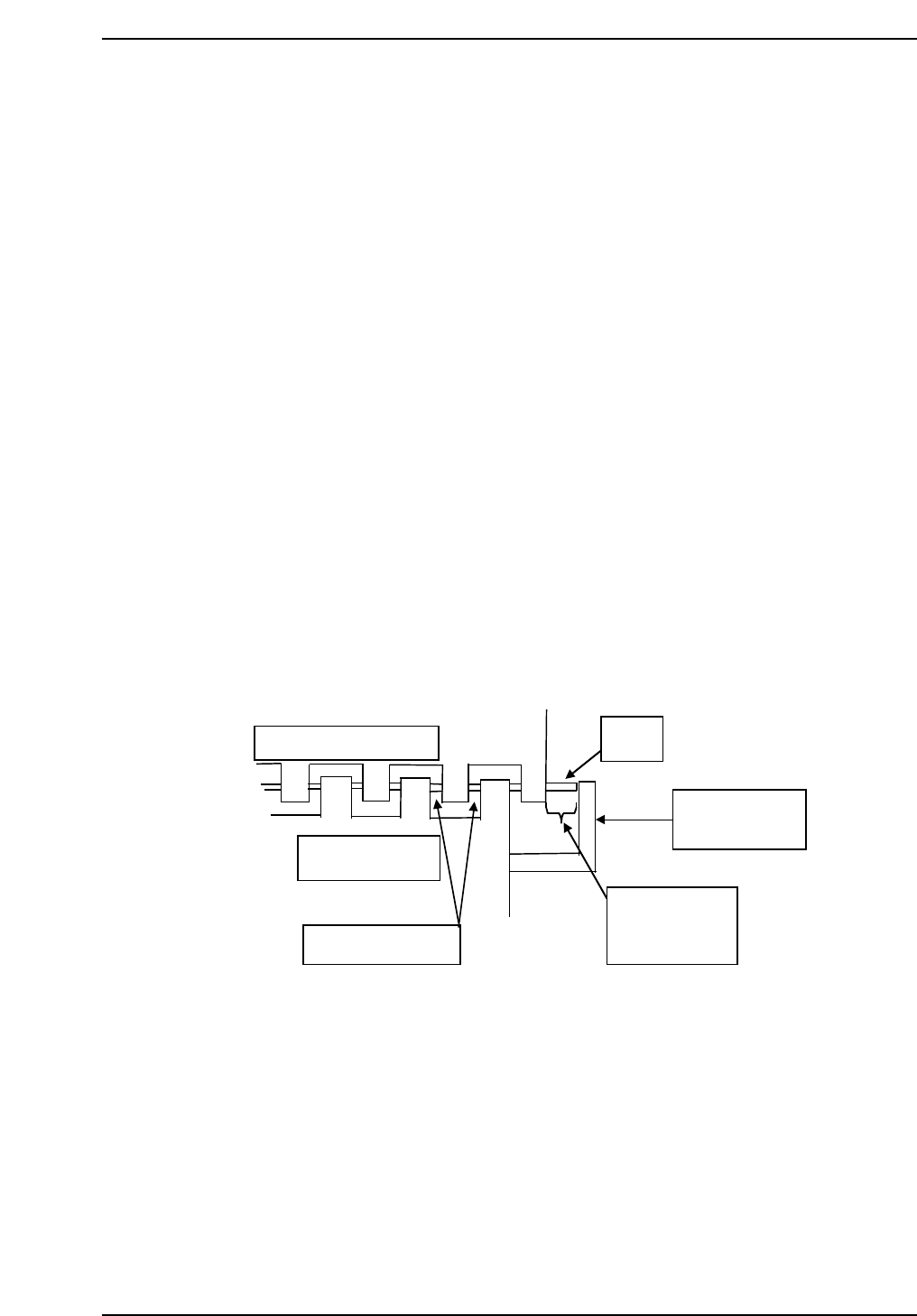
5. Move the MX-axis to the position where the second from the right jaw
aligns evenly within the right end cutout on the IN conveyor. Refer to
the illustration below.
6. Press [SET] → [PROPER] → [MAIN UNIT] → [ETC] → [MANIPULATE]
→ [PICKUP MX] → [SET] to record the value in Proper data.
Reference jaw
In-conveyor
Same clearance
QP132T1003
PCB
PCB stopper
7.75 mm
(– 0.5 mm)
Chapter 1
1.3 Measuring In Manipulator Proper Data and Adjustment
Edition 1.1 1-5 QP-132 Level 3 Tutorial
1.3.2 PCB Stopper Position
1. Press the EMERGENCY STOP button to shutdown the 200V.
2. Loosen the PCB stopper fixing bolts and move the unit toward the right.
3. Move the manipulator to Pcb_Pickup_Pos_MX.
4. Place a PCB on the IN conveyor.
5. Press [SET] → [MANUAL] → [I/O] → [STANDARD I/O] → [OUTPUT]
and use Y052 PCB LD HOOK OP to open the hook.
6. Y051 PCB LD DOWN to lower the manipulator.
7. Y053 PCB LD HOOK CL to clamp the PCB.
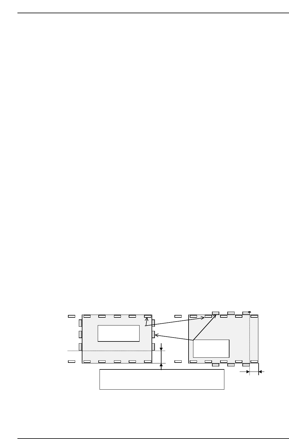
8. Move the stopper to set the clearance between the right edge of the
manipulator and the board to 7.75 mm (± 0.5 m).
9. Press I/O Y050 PCD LD UP to raise the manipulator.
10. Press I/O Y054 PCB TURN to rotate the manipulator.
11. Adjust the conveyor width.
12. Press Y051 PCB LD DOWN to lower the manipulator.
13. Adjust the speed controller so that the manipulator descends slowly.
14. Press [SET] → [MANUAL] → [I/O] → [STANDARD I/O] → [OUTPUT]
and Y051 PCB LD DOWN.
A
A
Lower plate of
the jaw
Manipulator
jaw
QP132T1004
Relationship between jaw plate & manipulator jaw:
A = 7.75 mm – 0.5 mm
Chapter 1
1.3 Measuring In Manipulator Proper Data and Adjustment
Edition 1.1 1-6 QP-132 Level 3 Tutorial