QP132三级参考手册.pdf.pdf - 第95页
6. Adjust the cylinder backward end sensor in the same manner as PFU unclamping side. 7.1.2 DX0, DY0 Pickup Position 1. Clamp the reference PFU to ST1. 2. Set the feeder jig (ACGPJ9070) to slot ST1, on PM1. 3. Set a nozz…

7.1 Measuring PFU Proper Data and
Adjustment
Required Jigs: Dummy Clamp Jig (Z9314CGQJ0161)
Feeder Jig (ACGPJ9070)
Nozzle Jig (ACGPJ9021)
7.1.1 PFU Clamper Adjustment
Speed Controller
1. Adjust the speed controllers located on the left bottom door on the front
side of the machine.
PFU Clamp: 2 turns from the fully closed position.
PFU Unclamp: 1.5 turns from the fully closed position.
2. Remove the bottom cover of the clamper and press [SET] → [MANUAL]
→ [I/O] → [STANDARD I/O] → [OUTPUT] and select I/O to unclamp.
3. Move both sensors and check the input signal.
Note: Both left and right clamper cylinder sensors need to be ON when clamped.
4. Move the cylinder forward end sensor positions one by one to find the
position.
[IN-Side] [OUT-Side]
X034 PFU1 CLP Y040 PFU1 CLAMP
X035 PFU1 UNCLP Y041 PFU1 UNCLAMP
X036 PFU2 CLP Y042 PFU2 CLAMP
:: : :
X03B PFU4 UNCLP Y047 PFU4 UNCLAMP
5. Clamp dummy clamp jig (Z9314CGQJ0161) using I/O.
Chapter 7 7.1 Measuring PFU Proper Data and Adjustment
Edition 1.1 7-1 QP-132 Level 3 Tutorial
6. Adjust the cylinder backward end sensor in the same manner as PFU
unclamping side.
7.1.2 DX0, DY0 Pickup Position
1. Clamp the reference PFU to ST1.
2. Set the feeder jig (ACGPJ9070) to slot ST1, on PM1.
3. Set a nozzle jig (ACGPJ9021) to holder A and measure the Proper data.
4. Measure PM2_S1, PM3_S1, and PM4_S1 in the same manner.
5. Clamp the reference PFU to each ST and calibrate.
6. Calibrate the rest of the PFU’s accordingly.
7. Calculate the average value of DX0 and DY0 for each PM. Set the value
to Proper, DX0 and DY0.
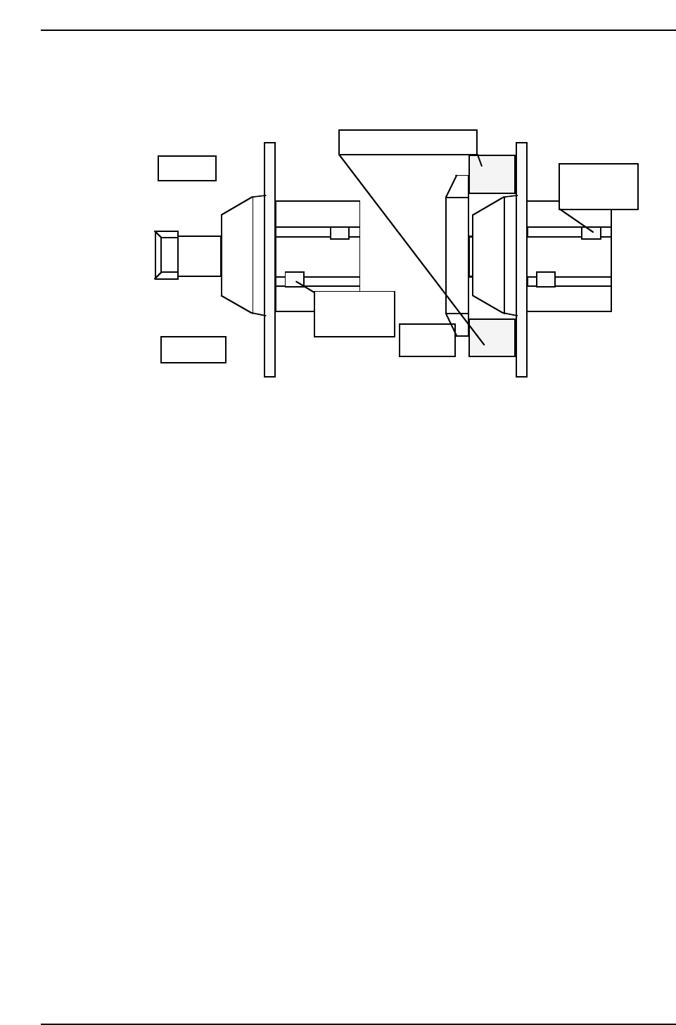
QP132T7001
Unclamp
PFU dummy clamp jig
M/C front
Unclamp
check sensor
At
clamping
Clamp check
sensor
Chapter 7 7.1 Measuring PFU Proper Data and Adjustment
Edition 1.1 7-2 QP-132 Level 3 Tutorial

7.2 Training Evaluation
Circle the most appropriate answer from the list below.
(1) To calculate Pickup Position DX0, DY0:
a. measuring positions of all the PFU’s are required.
b. measuring positions of all the modules are required.
c. measuring positions of all the PFU’s on all the modules are
required.
(2) PFU dummy clamp jig is used to measure:
a. PFU clamper forward end sensor.
b. PFU clamper backward end sensor.
c. Both a and b.
(3) To measure Pickup Position DX0, DY0, move the head by:
a. hand.
b. inching.
c. command.
(4) How many PFU clamper forward end sensors on one QP132?
a. 4
b. 8
c. 16
(5) To measure Pickup Position DX, DY0, install nozzle jig on:
a. nozzle holder E.
b. nozzle holder F.
c. nozzle holder B.
Chapter 7 7.2 Training Evaluation
Edition 1.0 7-3 QP-132 Level 3 Tutorial