QP132三级参考手册.pdf.pdf - 第83页
6.2 Measuring Parts Camera Proper Data and Adjustment 6.2.1 Delta and Parts Camera Pixel 1. Attach a resolution jig (ACGPJ9060) to holder A. 2. Set a dial indicator on the side of jig. 3. Move the X-axis using the inchin…
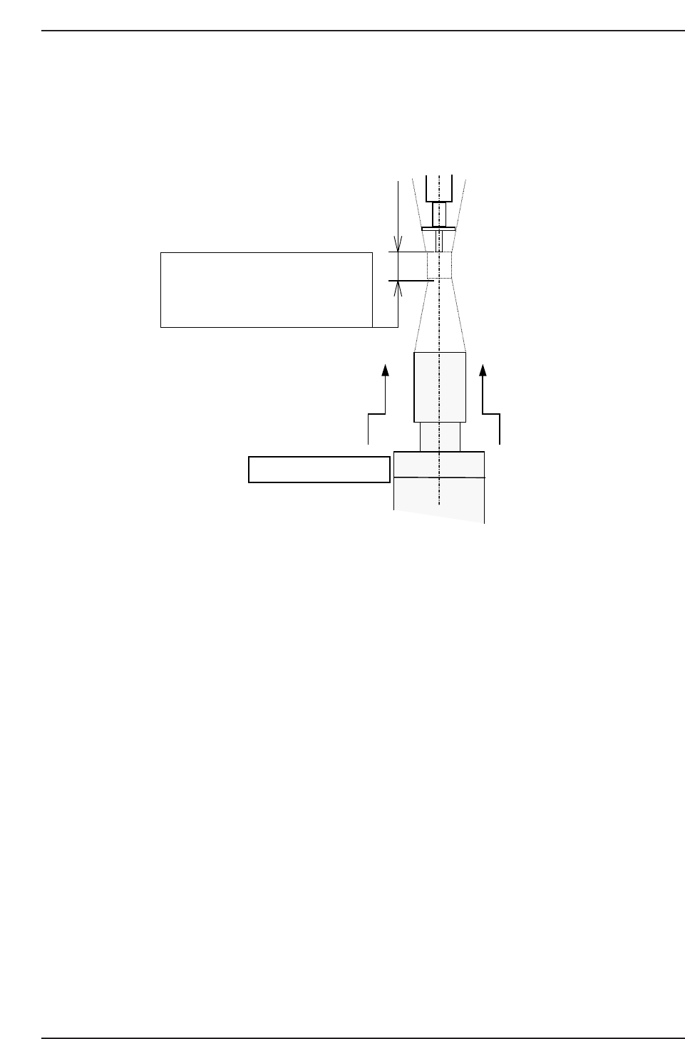
11. Raise the camera 0.5 mm from the focused position.
Note: Special lenses are used by the QP132 Parts cameras. Therefore, the focus distance is
about 6.0 mm. Do not lower the camera to focus. Move the unit upward from the
bottom.
QP132T6001
The focus area of parts camera has
approx. 6.0 mm.
Then adjust the nozzle tip until it is
just focused.
Focus from the bottom.
Chapter 6 6.1 Replacing Parts Camera
Edition 1.1 6-2 QP-132 Level 3 Tutorial
6.2 Measuring Parts Camera Proper Data and
Adjustment
6.2.1 Delta and Parts Camera Pixel
1. Attach a resolution jig (ACGPJ9060) to holder A.
2. Set a dial indicator on the side of jig.
3. Move the X-axis using the inching keys. Rotate Q and the placing head
and position the side of jig to parallel to the X-axis.
Tolerance : 0.01 mm
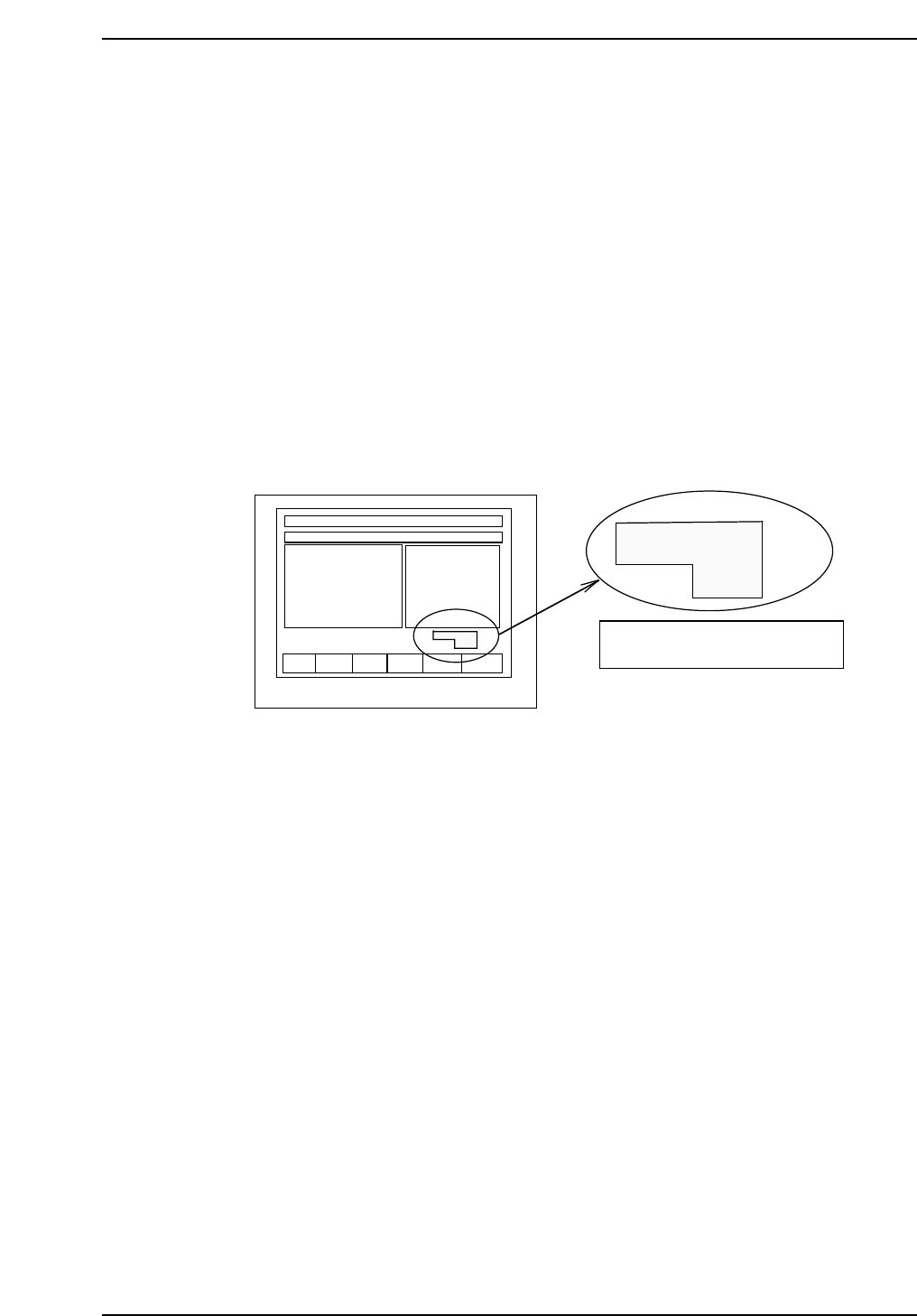
Note: When using the inching keys, check the desired PM. Check the jog display at the bottom
right of the monitor.
4. Press [SET] → [PROPER] → ID No. → [PM] → select the module to be
focused → [FINISH] → [Part Camera] → [Crosshair display] to display
the image.
5. Move the resolution jig to the center of the camera using the inching
keys.
6. Press [SET] → [PROPER] → Enter ID No. → [PM] → select the module →
[Part Camera] → [Resolution] → START.
Delta X: ± 50.0 um
Delta Y: ± 50.0 um
Delta Q: less than ± 0.050 deg.
X: 24.500 ± 0.5 um
Y: 24.500 ± 0.5 um
7. Adjust the camera height and angle.
8. Re-tighten and check the resolution several times.
F1 F2 F3 F4 F5 F6
jog X Y θ
PM01
Check the axis to be jogged and
PM no. in this display.
QP132T6002
Chapter 6
6.2 Measuring Parts Camera Proper Data and Adjustment
Edition 1.1 6-3 QP-132 Level 3 Tutorial
6.2.2 Camera Center
1. Press [SET] → [PROPER] → ID No. → [PM] → select the module →
[FINISH] → [Part Camera] → [Crosshair display] to display an image.
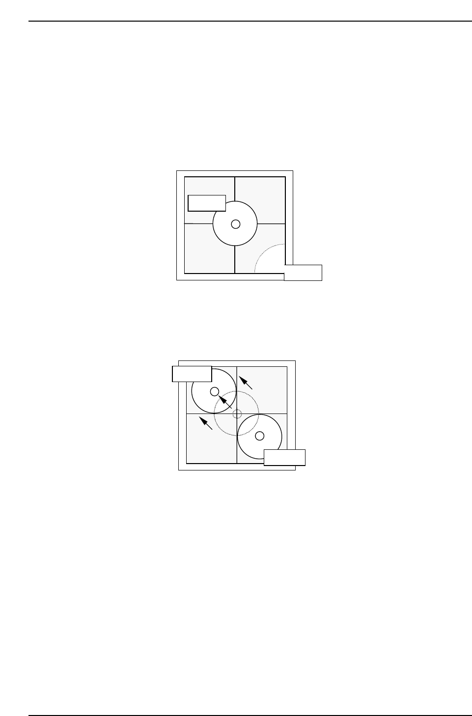
2. Attach a 1.3 diameter nozzle to holder A, B, C and D.
3. Use the inching keys to move reference nozzle A to the camera center.
4. Press [Part Camera] → [Camera Center] → Select the nozzle AB →
[EXECUTE]. The nozzle will move between nozzle A and B to auto-
calibrate.
5. Use the inching keys to move reference nozzle D to the camera center.
6. Press [Part Camera] → [Camera Center] → Select the nozzle CD →
[EXECUTE]. The nozzle will move between nozzle C and D to auto-
calibrate.
QP132T6004
Nozzle A
Nozzle B
QP132T6003
Nozzle A
Nozzle B
Chapter 6
6.2 Measuring Parts Camera Proper Data and Adjustment
Edition 1.1 6-4 QP-132 Level 3 Tutorial