3OM-1064-001.pdf - 第12页
Placement Head Check whether the vacuum filter of the placement is stained or clogged. *4 Refer to “Head” in “6. Monthly Maintenance of Section 1 in V olume 4” and inspect the filter . If necessary , replace the filter w…
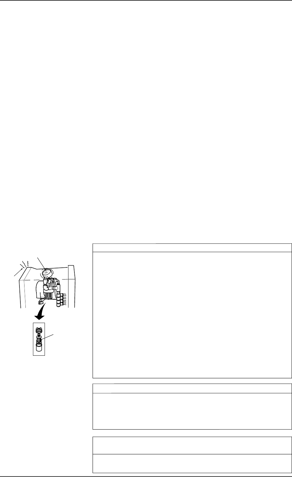
Vacuum Pressure System
Check whether the vacuum pressure is correctly adjusted. *1
Set the operation mode to “PLACE” by pressing the [PASS/PLACE
CHANGE] key at the “AUTO OPN. SUB-MENU” display and turn
off all vacuum valves ([LA1-AXIS VACUUM/VACUUM BLOW],
[LA2-AXIS VACUUM/VACUUM BLOW], [LB1-AXIS VACUUM/
VACUUM BLOW], and [LB2-AXIS VACUUM/VACUUM BLOW]
Keys).
Confirm that “OFF” is set in the “STATUS” text boxes at the
“MANUAL SUBSYSTEM OPERATION” display.
Confirm that the vacuum pressure is -93 kPa (70 cmHg) or more
(Vacuum valve fully closed).
When the vacuum pressure is too low, it is required to replace the
vacuum pump with a new one.
Consult our sales personnel for the detailed information on how to
replace or repair the vacuum pump.
Check whether the vacuum pump is producing any abnormal sound. *2
Catch the sound of the vacuum pump and confirm that the sound is
not abnormal.
When abnormal sound is produced, consult our sales personnel for
the countermeasures.
Check whether the filter of the vacuum pump is stained or clogged.
*3
Refer to “Vacuum Pressure System” in “8. Maintenance (Every 3
Months) of Section 1 in Volume 4” and inspect the filter.
1.1 Confirmation and Countermeasures against Low
Component Pick-Up Rate
1.1.1 Confirmation of Low Component Pick-Up Rate (Handling
Errors)
• Before confirming each item, check the following management information
and grasp the contents, the frequency, and the trend of pick-up errors.
(1) Machine Performance Data and Component Pick-Up/Placement In-
formation in Management Data
(2) Nozzle Management Data in Management Data
(3) Head Management Data in Management Data
(4) Handling Error per Feeder Location in Pattern Program Management
Data
(5) Recall Handling Error
(6) Recall Component Recognition Error
Refer to “4. RECALL MESSAGES of Section 3 in Volume 4” for the de-
tailed information on (1) through (4).
Refer to “3. MANAGEMENT DATA Display of Section 3 in Volume 4”
for the detailed information on (5) and (6).
1.1.2 Countermeasures against Frequent Pick-Up Errors
*1
*3
*2
0005-002 1-3 Tg0248-PM-ER
1. Cause and Remedy of Simple Trouble
Placement Head
Check whether the vacuum filter of the placement is stained or
clogged. *4
Refer to “Head” in “6. Monthly Maintenance of Section 1 in Volume
4” and inspect the filter. If necessary, replace the filter with a new
one.
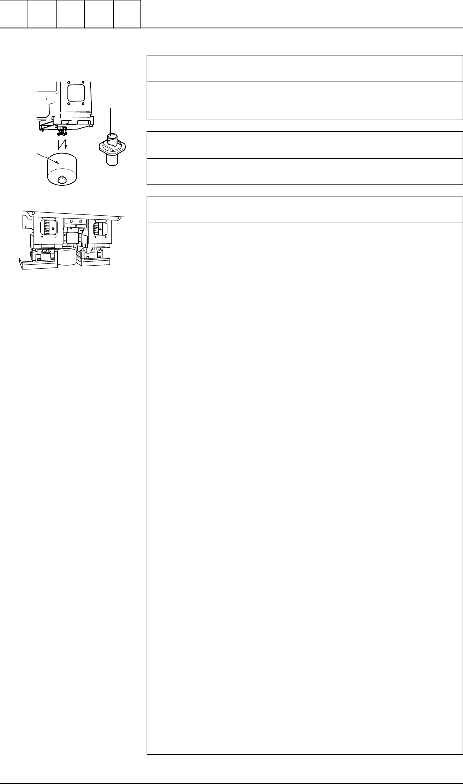
Check whether the internal part of the vacuum nozzle is stained
or clogged. *5
Refer to “Nozzle Stocker” in “6. Monthly Maintenance of Section 1
in Volume 4” and inspect the nozzles. If necessary, clean them.
Check whether the solenoid valves for vacuum and blowing are
correctly changed over. *6
Follow the two check procedures described below.
Items Required for Confirmation
• MA04 Nozzle
• Small Piece of Paper (Approx. 10 × 10 mm)
Notes: (a) Sebum nor oil, etc., should not adhere to the surface
of the diffusion plate of the vacuum nozzle.
(b) Detach the feeder before confirmation.
Procedure for Confirmation (Air Supply: “OFF”)
(1) Open the “ZEROING OPERATION” display and zero the X/Y
beam. (Hierarchical Sequence: “MANUAL MODE” Display
→ “ZEROING OPERATION” Display)
(2) Open the “MANUAL NOZZLE CHANGE OPERATION” dis-
play and replace the vacuum nozzle (the nozzle of the place-
ment head to be checked) with the MA04 one. (Hierarchical
Sequence: “MANUAL MODE” Display → “MANUAL
NOZZLE CHANGE OPERATION” Display)
(3) Open the “MANUAL SUBSYSTEM OPERATION” display.
Select the [BEAM-A AIR SUPPLY] or the [BEAM-B AIR SUP-
PLY] key and press the [MOVE] button to set to “OFF”. (Hier-
archical Sequence: “MANUAL MODE” Display → “MANUAL
SUBSYSTEM OPERATION” Display)
(4) Open the “MANUAL AXIS OPERATION” display and move
the X/Y beams until they can be reached by hands. (Hierarchi-
cal Sequence: “MANUAL MODE” Display → “MANUAL
AXIS OPERATION” Display)
(5) Set the [OPERATION/SET UP] switch on the checked side to
the “SET UP” side.
(6) Press the [READY ] button on the checked side and release the
electromagnetic locks of the supply cover and the safety bar.
(7) Open the supply cover on the checked side.
(8) Open the “MANUAL SUBSYSTEM OPERATION” display and
press the [L**-AXIS VACUUM/BLOW] key to set the “BLOW”
mode. (Hierarchical Sequence: “MANUAL MODE” Display →
“MANUAL SUBSYSTEM OPERATION” Display)
(9) Put a small piece of paper on your palm and bring it close to the
end of the vacuum nozzle. Confirm that the paper does not move
at all.
Confirm that the paper is picked up when the [L**-AXIS
VACUUM/BLOW] key is pressed again to set the
“VACUUM”mode.
*4
*5
Cut out the portion above
to use. (10
× 10 mm)
1. Cause and Remedy of Simple Trouble
0005-002 1-4 Tg0248-PM-ER

Procedure for Confirmation (Air Supply: “ON”)
(1) Open the “ZEROING OPERATION” display and zero the X/Y
beam. (Hierarchical Sequence: “MANUAL MODE” Display →
“ZEROING OPERATION” Display).
(2) Open the “MANUAL NOZZLE CHANGE OPERATION” dis-
play and replace the vacuum nozzle (the nozzle of the place-
ment head to be checked) with the MA04 one. (Hierarchical
Sequence: “MANUAL MODE” Display → “MANUAL
NOZZLE CHANGE OPERATION” Display)
(3) Open the “MANUAL SUBSYSTEM OPERATION” display.
Select the [BEAM-A AIR SUPPLY] or the [BEAM-B AIR SUP-
PLY] key and press the [MOVE] button to set to “ON”. (Hierar-
chical Sequence: “MANUAL MODE” Display → “MANUAL
SUBSYSTEM OPERATION” Display)
(4) Open the “MANUAL AXIS OPERATION” display and move
the X/Y beams until they can be reached by hands. (Hierarchi-
cal Sequence: “MANUAL MODE” Display → “MANUAL
AXIS OPERATION”Display).
(5) Set the [OPERATION/SET UP] switch on the checked side to
the “SET UP” side.
(6) Press the [READY ] button on the checked side and release the
electromagnetic locks of the supply cover and the safety bar.
(7) Open the supply cover on the checked side.
(8) Open the “MANUAL SUBSYSTEM OPERATION” display and
press the [L**-AXIS VACUUM/BLOW] key to set the
“VACUUM BLOW” mode. (Hierarchical Sequence: “MANUAL
MODE” Display → “MANUAL SUBSYSTEM
OPERATION”Display)
(9) Put a small piece of paper on your palm and bring it close to the
end of the vacuum nozzle. Confirm that air is blown to the pa-
per.
Confirm that the paper is picked up when the [L**-AXIS
VACUUM/BLOW] key is pressed again to set the
“VACUUM”mode.
Refer to “Section 4 Manual Mode Menus in Volume 1” for the
detailed information on each display.
Check whether the hoses of the X/Y beams and the placement
heads are crushed or have any holes. *7
Refer to the management data and check the hose of the placement
head which has caused low component pick-up rate.
•
Confirm that the bundled or fixed part of the hoses is not crushed
or the vacuum is leaking.
•
Confirm that the connected parts of the hoses are not crushed nor
the vacuum is not leaking.
•
Confirm that the flat tubes are not bent.
•
Confirm that no hose in the cable bearer has a hole due to friction
and mechanical wear.
1. Cause and Remedy of Simple Trouble
0005-002 1-5 Tg0248-PM-ER