3OM-1064-001.pdf - 第275页
0103-001 4-54-8 Tg0248-PM-ER 5. Component Recognition Error Code and List of Error Messages Error Code Display A Display B 20672124 COMPONENT DETECTION ERROR P AR T OF COMPONENT OUTLINE IS OUT OF VISUAL FIELD FOR RECOGNI…
0103-001 4-54-7 Tg0248-PM-ER
5. Component Recognition Error Code and List of Error Messages
Error Code Display A Display B
20672106 COMPONENT DETECTION
ERROR
LEAD POSITION (LEAD ARRAY DIRECTION) WAS
OUT OF TOLERANCE.
20672122 COMPONENT DETECTION
ERROR
CONTRAST BETWEEN COMPONENT AND BACK-
GROUND IS TOO LOW.
When "AUTO" is set in the "RECOG DATA SET" data box, in the "RECOG DATA" data box +
"ENBL (AUTO)" in the "LEAD POS (LATL DIR) DETN" data box, tolerance is automatically set.
This error can be avoided by setting in the "RECOG DATA" data box + in the "RECOG DATA
SET" data box and "DISABLE" in the "LEAD POS (LATL DIR) DETN" data box.
When these parameters are set, no bent lead is detected.
(Cause 1) There is a bent lead.
(Cause 2) The lead width is not suitable.
(When the lead width tolerance is automatically set and a parameter smaller than the
actual width is set as the lead width, a smaller parameter (tolerance decreased as much
as the reduction of the lead width) is also set.)
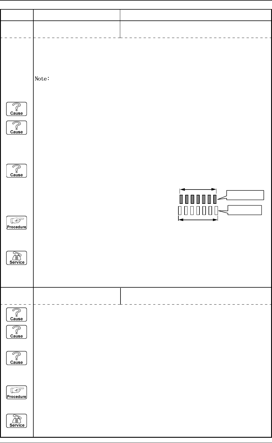
(Cause 3) The component thickness and the camera magnification are not suitable.
(When an image larger or smaller than the actual component size (component data) is
captured, the closer to both ends of the lead group the leads are located, the greater the
positional deviation becomes and such leads
are detected as "bent ones".)
(Reset Procedure in the case of Causes 1, 2 and 3)
Reset Procedure
(1) Press the [ZERO] button to return all the axes to
their original positions.
(2) Re-start.
(3) If the device can’t be re-started, contact our service personnel.
Actual Component
Component Data
(Cause 1) The lighting is not ON.
(Cause 2) The camera shutter speed is not suitable.
(In normal cases, the speed should be "5.0 to 11.0 ms".)
(Cause 3) The gain and level of the camera are not suitable.
(In normal cases, the gain should be "160 to 190" and the level "0 to 10".)
(Reset Procedure in the case of Causes 1, 2 and 3)
Reset Procedure
(1) Press the [ZERO] button to return all the axes to their original positions.
(2) Re-start.
(3) If the device can’t be re-started, contact our service personnel.
0103-001 4-54-8 Tg0248-PM-ER
5. Component Recognition Error Code and List of Error Messages
Error Code Display A Display B
20672124 COMPONENT DETECTION
ERROR
PART OF COMPONENT OUTLINE IS OUT OF VISUAL
FIELD FOR RECOGNITION.
20672123 COMPONENT DETECTION
ERROR
OUTLINE OF COMPONENT NOT FOUND.
20672125 COMPONENT DETECTION
ERROR
COMPONENT OUTLINE NOT FOUND.
20672126 COMPONENT DETECTION
ERROR
THE COMPONENT OUTLINE DOES NOT MATCH THE
CORRESPONDING DATA.
20672128 COMPONENT DETECTION
ERROR
POSITIONING ABORTED BECAUSE OF IMPROPER
COMPONENT HANDLING.
20672127 COMPONENT DETECTION
ERROR
THE CONTOUR OF COMPONENT DOES NOT MATCH
THE CORRESPONDING DATA.
(Cause 1) This is the device’s self-diagnostic message.
(Reset Procedure in the case of Cause 1)
Reset Procedure
(1) Press the [ZERO] button to return all the axes to their original positions.
(2) Re-start.
(3) If the device can’t be re-started, contact our service personnel.
(Cause 1) Improper parameters are set in the "X" and "Y" data boxes of the label "MOLD SIZE".
(Reset Procedure in the case of Cause 1)
Reset Procedure
(1) Press the [ZERO] button to return all the axes to their original positions.
(2) Re-start.
(3) If the device can’t be re-started, contact our service personnel.
(Cause 1) This is the device’s self-diagnostic message.
(Reset Procedure in the case of Cause 1)
Reset Procedure
(1) Press the [ZERO] button to return all the axes to their original positions.
(2) Re-start.
(3) If the device can’t be re-started, contact our service personnel.
0103-003 4-55 Tg0248-PM-ER
5. Component Recognition Error Code and List of Error Messages
Error Code Display A Display B
20672142 COMPONENT DETECTION
ERROR
UNSPECIFIED LEADS ARE DETECTED.
20672141 COMPONENT DETECTION
ERROR
LEAD NOT FOUND.
20672129 COMPONENT DETECTION
ERROR
THE OUTLINE CANNOT BE DETECTED AD-
EQUATELY.
(Cause 1) Improper parameters are set in the "X" and "Y" data boxes of the label "MOLD SIZE".
(Cause 2) The diameter of the selected nozzle is larger than the outline of the component.
(Cause 3) Improper parameters are set in the "X" and "Y" data boxes of the label "NOZZLE
OUTER SIZE" at the "NOZZLE TYPE DATA" display.
(Reset Procedure in the case of Causes 1, 2 and 3)
Reset Procedure
(1) Press the [ZERO] button to return all the axes to their original positions.
(2) Re-start.
(3) If the device can’t be re-started, contact our service personnel.
(Cause 1) No component is picked up.
(Cause 2) A different component (small component, etc.) is picked up.
(Cause 3) The lighting is not ON.
(Reset Procedure in the case of Causes 1, 2 and 3)
Reset Procedure
(1) Press the [ZERO] button to return all the axes to their original positions.
(2) Re-start.
(3) If the device can’t be re-started, contact our service personnel.
(Cause 1) The number of leads is not suitable.
(Cause 2) Objects shaped identically to the leads exist at both ends of the lead group.
(Cause 3) Dirt and dust have accumulated at both ends of the lead group.
(Reset Procedure in the case of Causes 1, 2 and 3)
Reset Procedure
(1) Press the [ZERO] button to return all the axes to their original positions.
(2) Re-start.
(3) If the device can’t be re-started, contact our service personnel.