3OM-1064-001.pdf - 第14页
Check whether the pick-up position is proper . *8 • Perform the teaching operation on the pick-up location at the “PICK- UP LOCA TION” display . (Hierarchical Sequence: “TEACH OFF- SET” Display → “PICK-UP LOCA TION” Disp…

Procedure for Confirmation (Air Supply: “ON”)
(1) Open the “ZEROING OPERATION” display and zero the X/Y
beam. (Hierarchical Sequence: “MANUAL MODE” Display →
“ZEROING OPERATION” Display).
(2) Open the “MANUAL NOZZLE CHANGE OPERATION” dis-
play and replace the vacuum nozzle (the nozzle of the place-
ment head to be checked) with the MA04 one. (Hierarchical
Sequence: “MANUAL MODE” Display → “MANUAL
NOZZLE CHANGE OPERATION” Display)
(3) Open the “MANUAL SUBSYSTEM OPERATION” display.
Select the [BEAM-A AIR SUPPLY] or the [BEAM-B AIR SUP-
PLY] key and press the [MOVE] button to set to “ON”. (Hierar-
chical Sequence: “MANUAL MODE” Display → “MANUAL
SUBSYSTEM OPERATION” Display)
(4) Open the “MANUAL AXIS OPERATION” display and move
the X/Y beams until they can be reached by hands. (Hierarchi-
cal Sequence: “MANUAL MODE” Display → “MANUAL
AXIS OPERATION”Display).
(5) Set the [OPERATION/SET UP] switch on the checked side to
the “SET UP” side.
(6) Press the [READY ] button on the checked side and release the
electromagnetic locks of the supply cover and the safety bar.
(7) Open the supply cover on the checked side.
(8) Open the “MANUAL SUBSYSTEM OPERATION” display and
press the [L**-AXIS VACUUM/BLOW] key to set the
“VACUUM BLOW” mode. (Hierarchical Sequence: “MANUAL
MODE” Display → “MANUAL SUBSYSTEM
OPERATION”Display)
(9) Put a small piece of paper on your palm and bring it close to the
end of the vacuum nozzle. Confirm that air is blown to the pa-
per.
Confirm that the paper is picked up when the [L**-AXIS
VACUUM/BLOW] key is pressed again to set the
“VACUUM”mode.
Refer to “Section 4 Manual Mode Menus in Volume 1” for the
detailed information on each display.
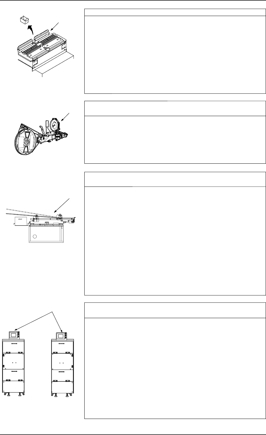
Check whether the hoses of the X/Y beams and the placement
heads are crushed or have any holes. *7
Refer to the management data and check the hose of the placement
head which has caused low component pick-up rate.
•
Confirm that the bundled or fixed part of the hoses is not crushed
or the vacuum is leaking.
•
Confirm that the connected parts of the hoses are not crushed nor
the vacuum is not leaking.
•
Confirm that the flat tubes are not bent.
•
Confirm that no hose in the cable bearer has a hole due to friction
and mechanical wear.
1. Cause and Remedy of Simple Trouble
0005-002 1-5 Tg0248-PM-ER
Check whether the pick-up position is proper. *8
•
Perform the teaching operation on the pick-up location at the “PICK-
UP LOCATION” display. (Hierarchical Sequence: “TEACH OFF-
SET” Display → “PICK-UP LOCATION” Display)
•
Use the [PICK FROM FDR (MANUAL)] key at the “COMPO-
NENT RECOG TEST” display or open the “MANUAL AXIS
OPERATION” display to move the vacuum nozzle to the pick-up
position. (Hierarchical Sequence: “MANUAL MODE” Display →
“MANUAL AXIS OPERATAION” Display).
Confirm that the pick-up position of the placement head is cor-
rectly aligned with the component supply position of the feeder.
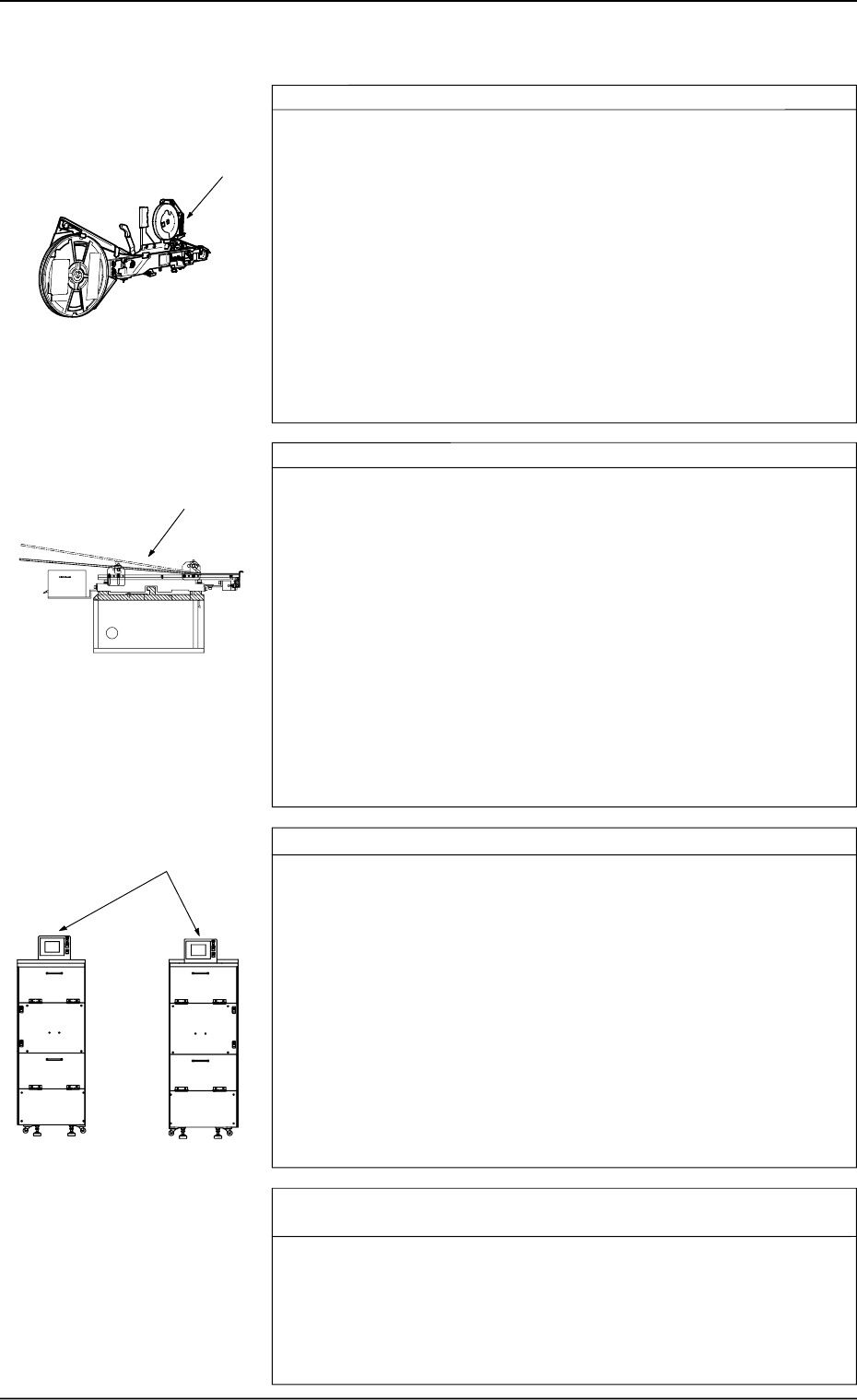
Check whether the components are correctly fed from the Tape
Feeder. *9
•
Move each part of the tape feeder manually and confirm that each
movement is normal.
•
Move the tape feeder manually and confirm that the tape can be
fed as far as required.
•
Check visually whether the feed lever of the feeder base moves
normally.
Check whether the components are correctly fed from the Vibra-
tory
Stick Feeder. *10
•
Check whether the vibratory stick feeder is installed correctly.
Check visually how it is installed.
If the stick is not bent correctly, the components cannot be fed
smoothly.
•
Check whether the feed time in the component library data is
proper.
Check this visually.
If the feed time is not proper, the machine takes a pick-up action
before a component is not fed completely.
•
Check whether the escape action (action of air cylinder) takes
place normally.
If not, the picked component may be off-positioned or fall down
while it is moving up.
Check visually how the escape action takes place.
Check whether the components are correctly fed from the Multi-
Layer Tray Feeder (Option). *11
•
Attachment of Multi-Layer Tray Feeder
If the multi-layer tray feeder is not attached correctly to the tray
pallet, components cannot be picked up normally.
Confirm that the feeder is attached without any leeway.
•
Transfer of Pallet from Elevator (how the pallet is pulled out
from the elevator)
If the pallet is not transferred smoothly from the elevator, the com-
ponents may deviate from the correct position.
Check visually whether the pallet is transferred smoothly.
•
Tray Data (Parameters) in Component Library Data
Confirm that the tray data in the component library data is proper.
•
Tray Offset Values
Confirm that the tray offset values are correctly set.
*10
*8
*11
FP-5021R
FP-5021L
1. Cause and Remedy of Simple Trouble
0005-002 1-6 Tg0248-PM-ER
*9
Tape Feeder: *1
•
Check whether a tape feeder suitable for the selected com-
ponents is used.
Check the type and specifications of the tape feeder and confirm
that a tape feeder suitable for the selected tape is used.
•
Peel off the cover tape and turn over the carrier tape to con-
firm that the components in the cavities fall down due to their
own weight.
Confirm that the components do not stick to the tape.
Confirm that the tape is free of static electricity.
Confirm that the taping is conformable to the specified limits.
•
Check whether the peel strength of the cover tape is proper.
Refer to the instruction manual of the tape feeder and check the
peel strength.
Vibratory Stick Feeder: *2
•
Check whether the vibratory stick feeder is installed correctly.
Check visually how it is installed.
If the stick is not bent correctly, the components cannot be fed
smoothly.
•
Check whether the feed time in the component library data is
proper
Check this visually.
If the feed time is not proper, the machine takes a pick-up action
before a component is not fed completely.
•
Check whether the escape action (action of air cylinder) takes
place normally.
If not, the picked component may be off-positioned or fall down
while it is moving up.
Check visually how the escape action takes place.
Multi-Layer Tray Feeder (Option): *3
•
Attachment of Multi-Layer Tray Feeder
If the multi-layer tray feeder is not attached correctly to the tray
pallet, components cannot be picked up normally.
Confirm that the feeder is attached without any leeway.
•
Transfer of Pallet from Elevator (how the pallet is pulled out
from the elevator)
If the pallet is not transferred smoothly from the elevator, the com-
ponents may deviate from the correct position.
Check visually whether the pallet is transferred smoothly.
•
Tray Data (Parameters) in Component Library Data
Confirm that the tray data in the component library data is proper.
•
Tray Offset Values
Confirm that the tray offset values are correctly set.
Check whether the pick-up level in the component library data is
proper. *4
•
Check visually whether the pick-up level in the component library
data is proper. Refer to the component pick-up menus in the com-
ponent recognition test menus.
•
Perform the teaching operation on the pick-up location at the “PICK-
UP LOCATION” display. (Hierarchical Sequence: “TEACH OFF-
SET” Display → “PICK-UP LOCATION” Display)
*1
*2
*3
FP-5021R
FP-5021L
1.1.3 Frequently-Caused Pick-Up Errors on Specific Components
0005-002 1-7 Tg0248-PM-ER
1. Cause and Remedy of Simple Trouble