3OM-1064-001.pdf - 第290页
5. Component Recognition Error Code and List of Error Messages 0103-002 4-59-1 Tg0248-PM-ER Error Code Display A Display B 20XXXXXX COMPONENT DETECTION except the ERROR above- described codes ETC. (Cause 1) This is the d…
0103-004 4-59 Tg0248-PM-ER
5. Component Recognition Error Code and List of Error Messages
Error Code Display A Display B
20672668 COMPONENT DETECTION
ERROR
SOME LEADS CANNOT BE DETECTED.
(Cause 1) Some leads are missing.
(Cause 2) The size of the component is not correct.
Wrong parameters are set at the "CMPNT LIBRARY [SHAPE]" displays.
Wrong parameters are set for "LEAD TYPE DATA" and "LEAD GROUP DATA" at
the "CMPNT LIBRARY [SHAPE]" display.
(Cause 3) A clear image of the component cannot be captured.
(Reset Procedure in the case of Causes 1, 2 and 3)
Reset Procedure
(1) Press the [ZERO] button to return all the axes to their original positions.
(2) When the registered leads are captured by the camera and part of the nozzle covers some of
the captured leads, register the covered leads as missing ones (regarding them as non-objec-
tive ones for detection), using "EXTENDED SETTING" for the flat-packaged components
and "LEAD GROUP DATA" for the deform (leaded) components.
(3) When a clear image of the leads cannot be captured (unevenness, etc.), "BACK LTG." must
be set in the "LTG MODE" data box in place of "FRONT LTG.".
(4) Set "MANUAL (FRONT LTG)" in the "LTG MODE" data box and change the parameters in
the "LTG PATT" and "BRT" data boxes at the "CMPNT LIBRARY [RECOG]" display such
that an image of the leads can be captured more evenly.
(5) Re-start.
(6) If the device can’t be re-started, contact our service personnel.
5. Component Recognition Error Code and List of Error Messages
0103-002 4-59-1 Tg0248-PM-ER
Error Code Display A Display B
20XXXXXX COMPONENT DETECTION
except the ERROR
above-
described
codes
ETC.
(Cause 1) This is the device’s self-diagnostic message.
(Reset Procedure in the case of Cause 1)
Reset Procedure
(1) Press the [ZERO] button to return all the axes to their original positions.
(2) Re-start.
(3) If the device can’t be re-started, contact our service personnel.
THE LEADS LOCATED AT THE ENDS OF THE AR-
RAYED LEADS CANNNOT BE DETERMINED.
20672801 COMPONENT DETECTION
ERROR
WIDTH OF LEAD EXCEEDS THE TOLERANCE.
20672800 COMPONENT DETECTION
ERROR
LEAD POSITION (LEAD LENGTH DIRECTION) WAS
OUT OF TOLERANCE.
20672856 COMPONENT DETECTION
ERROR
THE DETECTED BALL POSITION DOES NOT MATCH
THE POSITION DATA.
20672855 COMPONENT DETECTION
ERROR
THE DETECTED BALL POSITION DOES NOT MATCH
THE POSITION DATA.
20672670 COMPONENT DETECTION
ERROR
SOME BALLS CANNOT BE DETECTED.
20672859 COMPONENT DETECTION
ERROR
BALL POSITION WAS OUT OF TOLERANCE.
20672858 COMPONENT DETECTION
ERROR
UNSPECIFIED BALLS ARE DETECTED.
20672881 COMPONENT DETECTION
ERROR
COMPONENT OUTWARD LENGTH Y WAS OUT OF
TOLERANCE.
20672880 COMPONENT DETECTION
ERROR
COMPONENT OUTWARD LENGTH X WAS OUT OF
TOLERANCE.
20672857 COMPONENT DETECTION
ERROR
6. Nozzle Recognition Error Code and List of Error
Messages
Shown below are the contents of error codes which might be issued in the
nozzle recognition processing.
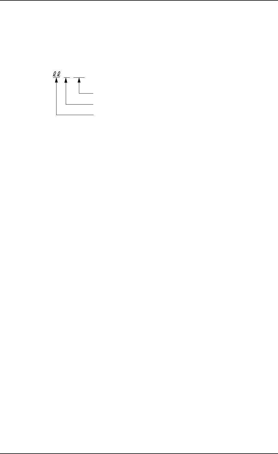
Detail Code
ID Code of Recognition Function (30)
Error ID Code (00)
ccccss
0005-002 4-60 Tg0248-PM-ER
6. Nozzle Recognition Error Code and List of Error Messages