DECAN_S1_Administrator′s_Guide(Eng_Ver1.5)_Print.pdf - 第174页
7-10 Next Generation, Multi-Functional Plac er DECAN S1 Administrator’s Guide Caution If Depth Z is set, it is reflected in the pickup height (Pickup Z). Therefore, when Depth Z is se t, do not modify Pickup Z manually i…
7-9
Part Registration
<Head> selection control
Of the entire image, it shows an image in the area corresponding to the selected
head in the SMVision window.
<5. Part Data> group
Set the data including the component size.
<X> edit box
Set the component size in X direction.
<Y> edit box
Set the component size in Y direction.
<Thickness> edit box
Set the height (thickness) of the component.
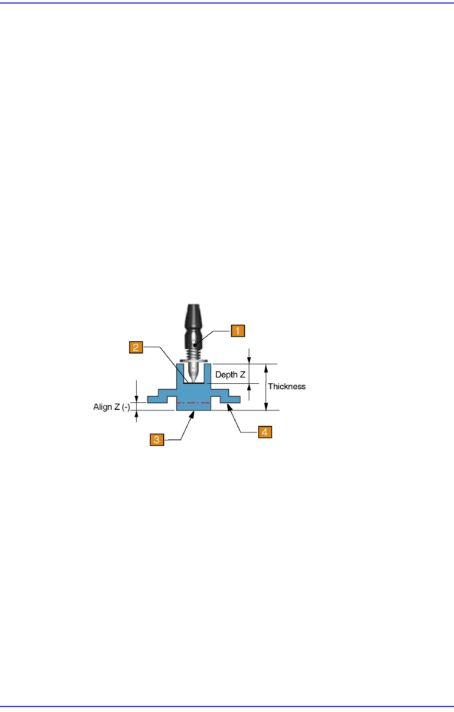
<Depth Z> edit box
Set the depth of the groove on top of the component. Unless warranted by a
special purpose, set to “0”. For a part that cannot be picked up at its top surface,
this parameter must be set.
1: Nozzle
2: Pickup surface of part
3: Bottom surface of part
4: Placement surface of part
7-10
Next Generation, Multi-Functional Placer DECAN S1 Administrator’s Guide
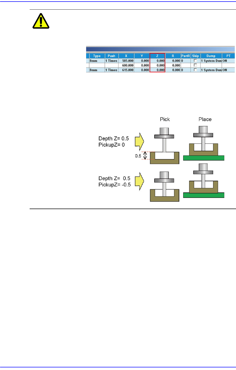
Caution If Depth Z is set, it is reflected in the pickup height (Pickup
Z). Therefore, when Depth Z is set, do not modify Pickup Z
manually in the ‘Feeder Base’ dialog box.
For parts whose pickup height must be modified such as
parts fed by embossed tape, modify the ‘Pickup Data’ of the
common parameter of the part. (Refer to “Pickup Data” tab
dialog box in the “7.1 New Part Registration”.)
<Register> button
Adds the set component data to the PCB part list.
<Close> button
Closes the dialog box.
<5. Align Data> group
Set the component align data. The edit screen for the align data selected in <2. Align
Type> and <3. Package Group> are displayed in this group.
The display is varied according to the data selected in the <3. Package Group>. Please
refer to section “7.1.2 ~ 7.1.8” for more information.
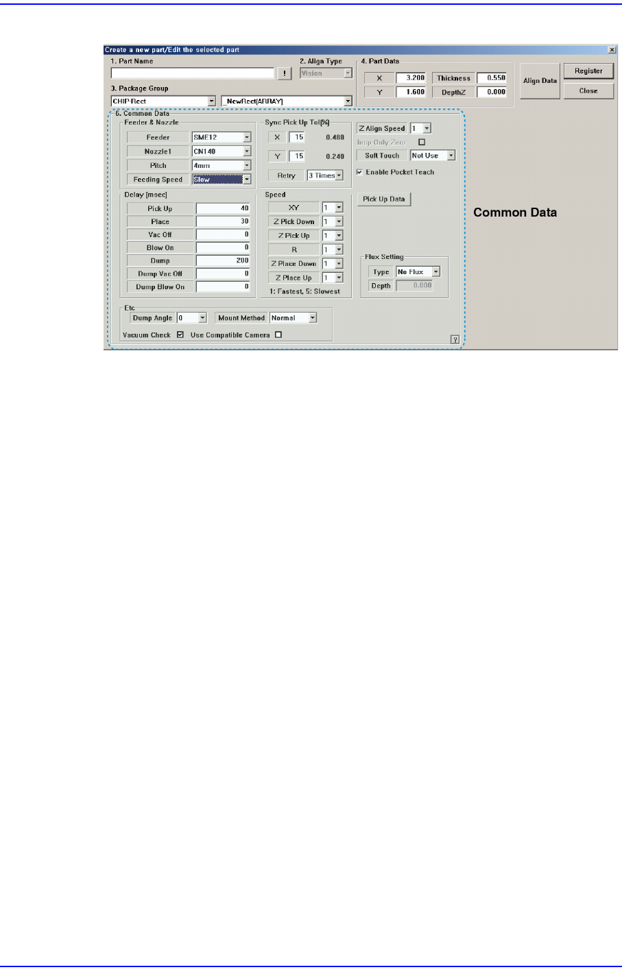
<Common Data> button
Sets the component data related to the machine. When this button is clicked on, the
following dialog box is displayed and the name of the button is changed to “Align
Data”.
7-11
Part Registration
Figure7.4 “Create a new part/Edit the selected part- Common Data” dialog box
<Feeder & Nozzle> group
<Feeder> combo box
Select the feeder type to supply components. Applicable feeder types are as
follows.
SM8L: Supply by 8mm SM Tape Feeder (Large).
SM8: Supply by 8mm SM Tape Feeder.
SM12: Supply by 12mm SM Tape Feeder.
SM16: Supply by 16mm SM Tape Feeder.
SM24: Supply by 24mm SM Tape Feeder.
SM32: Supply by 32mm SM Tape Feeder.
SM44: Supply by 44mm SM Tape Feeder.
SM56: Supply by 56mm SM Tape Feeder.
SM72: Supply by 72mm SM Tape Feeder.
SM88: Supply by 88mm SM Tape Feeder.
SME8L: Supplies parts to the motor driven 8 mm SM tape feeder(Large).
SME4_1P: Supplies parts to the motor driven 4 mm SM tape feeder(1Pitch).
SME8: Supplies parts to the motor driven 8 mm SM tape feeder.
SME12: Supplies parts to the motor driven 12 mm SM tape feeder.
SME16: Supplies parts to the motor driven 16 mm SM tape feeder.
SME24: Supplies parts to the motor driven 24 mm SM tape feeder.
SME32: Supplies parts to the motor driven 32 mm SM tape feeder.