DECAN_S1_Administrator′s_Guide(Eng_Ver1.5)_Print.pdf - 第398页
14-16 Next Generation, Multi-Functional Plac er DECAN S1 Administrator’s Guide H1F-Z2: Z axis of spindle2 of the gantry H1F-Z3: Z axis of spindle3 of the head H1F-Z4: Z axis of spindle4 of the head H1F-Z5: Z axis of spin…
14-15
Machine Calibration
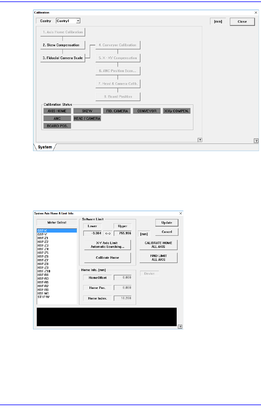
14.3.1. Axis Home Calibration
Sets the limit position of each axis to move. When this button is clicked on, the following
dialog box is displayed.
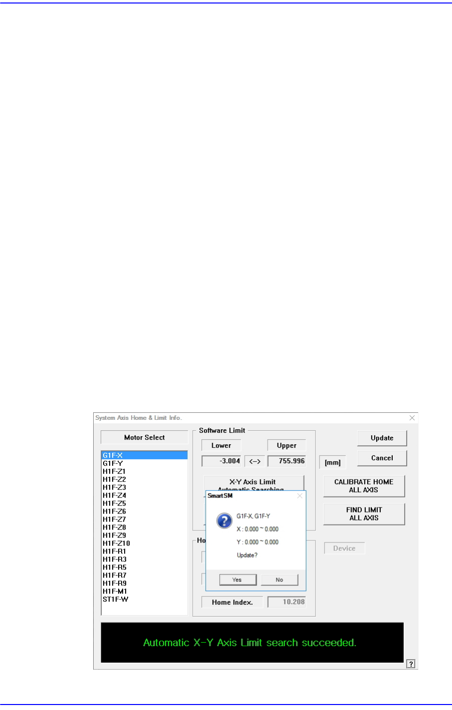
Figure14.7 “System Axis Limit Info.” dialog box
<Motor Select> list box
Select the motor axis for which to set the limit. Available axes are as follows.
G1F-X: X axis of the gantry
G1F-Y: Y axis of the gantry
H1F-Z1: Z axis of spindle1 of the gantry
14-16
Next Generation, Multi-Functional Placer DECAN S1 Administrator’s Guide
H1F-Z2: Z axis of spindle2 of the gantry
H1F-Z3: Z axis of spindle3 of the head
H1F-Z4: Z axis of spindle4 of the head
H1F-Z5: Z axis of spindle5 of the head
H1F-Z6: Z axis of spindle6 of the head
H1F-Z7: Z axis of spindle7 of the head
H1F-Z8: Z axis of spindle8 of the head
H1F-Z9: Z axis of spindle9 of the head
H1F-Z10: Z axis of spindle10 of the head
H1F-R1: Theta axis (H1, H2) of the head
H1F-R3: Theta axis (H3, H4) of the head
H1F-R5: Theta axis (H5, H6) of the head
H1F-R7: Theta axis (H7, H8) of the head
H1F-R9: Theta axis (H9, H10) of the head
H1F-M1: Mirror axis of the head
ST1F-W: Width control motor of the work station(F2)
<Software Limit> group
<X-Y Axis Limit Automatic Searching…> button
Finds the limit of the X and Y axes automatically and checks whether to apply the
changed value.

14-17
Machine Calibration
<Skew Compensation> button
Activated when selecting the Y axis. It is used to perform the skew compensation.
For further details, refer to “13.3.2 Skew compensation”.
<Head Limit Setting> button
Activated when selecting the Z axis. The function automatically measures the
limit value of the Z axis and checks whether or not to apply the changed value.
<Station Axis Limit Searching> button
This is activated when the conveyor width control motor is selected. The function
automatically measures the limit value of the conveyor width and checks whether
or not to apply the changed value.
<Calibrate Home> button
Automatically finds and reflects the home position of the motor selected from the
<Motor Select> list box.
<CALIBRATE HOME ALL AXIS> button
Automatically finds and reflects the home positions of all axes.
<FIND LIMIT ALL AXIS> button
Finds limit value of all axes.
<Home Info.> group
If the mirror axis is selected, the <Home Offset> edit box will be enabled. It is used to
perform calibration for the mirror axis.
<Update> button
Transmits the set data to the machine and closes the dialog box.
<Close> button
Ignores the set data and closes the dialog box.
Caution If calibration is done again, the machine might not operate
properly unless the items related to the equipment position,
such as pick up position, ANC, placement origin are taught
again as the home position is changed.
After calibration, be sure to teach the items related to
position again.