DECAN_S1_Administrator′s_Guide(Eng_Ver1.5)_Print.pdf - 第397页
14-15 Machine Calibration 14.3.1. Axis Home Calibration Sets the limit position of each axis to move. Wh en this button is clicked on, the following dialog box is displayed. Figure14.7 “System Axis Limit Info.” dialog bo…
14-14
Next Generation, Multi-Functional Placer DECAN S1 Administrator’s Guide
14.3. Calibration [F9]
Caution To obtain accurate calibration data, perform calibration after
operating the machine for 1 hour and 30 minutes.
Before measuring the Mount Offset of a micro component (e.g.,
0402 chip part) that is likely to cause a mounting shift due to
slight variations, do the following.
Allow the machine to warm up for 1 hour.
Measure the Mount Offset 30 minutes after warm up is
complete.
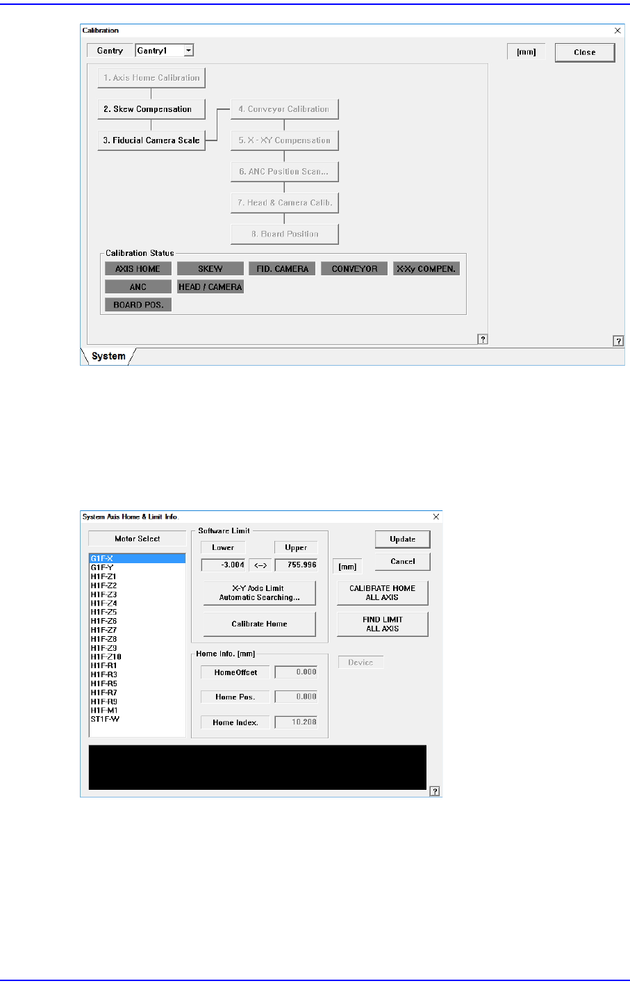
Used to perform calibrations related with the XY Gantry and camera.
The following are the works to be performed before performing calibration or those to be
performed in advance;
I/O Test
Mirror offset check and correction
Nozzle check and vacuum check option for system constant
Nozzle check and calibration tool option for system constant
System Constant No.[128](OPT_FIX_CAM_CALIB_METHOD) = 2
1: Camera Offset (Glass)
2: Camera Offset (Glass) + Camera Offset (Hole)
ANC type check
Pneumatic system check for any problem
The order in which the calibration is performed and the calibration tool needed to perform
the corresponding calibration is as follows;
Axis Home Calibration
Skew Compensation
Fiducial Camera Scale Calibration
Fiducial Cameras Offset Calibration
Conveyor Calibration
X-XY Compensation – Calibration Bar
ANC Position Scan
Head & Camera Calibration - CNT20, CN040, LightFly Nozzle, LightFix Nozzle,
Calibration Glass
Board Position
14-15
Machine Calibration
14.3.1. Axis Home Calibration
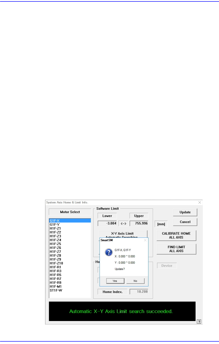
Sets the limit position of each axis to move. When this button is clicked on, the following
dialog box is displayed.
Figure14.7 “System Axis Limit Info.” dialog box
<Motor Select> list box
Select the motor axis for which to set the limit. Available axes are as follows.
G1F-X: X axis of the gantry
G1F-Y: Y axis of the gantry
H1F-Z1: Z axis of spindle1 of the gantry
14-16
Next Generation, Multi-Functional Placer DECAN S1 Administrator’s Guide
H1F-Z2: Z axis of spindle2 of the gantry
H1F-Z3: Z axis of spindle3 of the head
H1F-Z4: Z axis of spindle4 of the head
H1F-Z5: Z axis of spindle5 of the head
H1F-Z6: Z axis of spindle6 of the head
H1F-Z7: Z axis of spindle7 of the head
H1F-Z8: Z axis of spindle8 of the head
H1F-Z9: Z axis of spindle9 of the head
H1F-Z10: Z axis of spindle10 of the head
H1F-R1: Theta axis (H1, H2) of the head
H1F-R3: Theta axis (H3, H4) of the head
H1F-R5: Theta axis (H5, H6) of the head
H1F-R7: Theta axis (H7, H8) of the head
H1F-R9: Theta axis (H9, H10) of the head
H1F-M1: Mirror axis of the head
ST1F-W: Width control motor of the work station(F2)
<Software Limit> group
<X-Y Axis Limit Automatic Searching…> button
Finds the limit of the X and Y axes automatically and checks whether to apply the
changed value.