DECAN_S1_Administrator′s_Guide(Eng_Ver1.5)_Print.pdf - 第425页
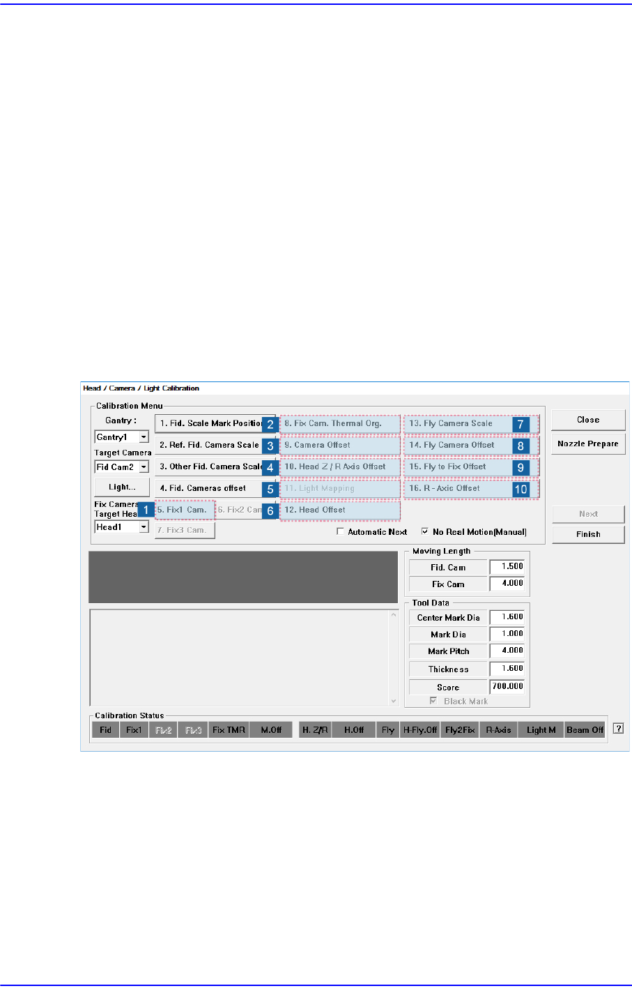
14-43 Machine Calibration Figure14.1 2 “Head / Camera/ L ight Calib ration” di alog box 1: Head/ Camera/ Light Calibration” dialog box <Calibration Menu> group Select an item to be calibrated. If you click the bu…
14-42
Next Generation, Multi-Functional Placer DECAN S1 Administrator’s Guide
14.3.8. Head & Camera Calibration
Perform the camera calibration function. The calibration sequence and tools necessary for
calibration are as follows.
1) Fix Camera Calibration (Scale & Rotation & Position) (CNT20 Nozzle)
2) Fix Cam. Thermal Org.
3) Camera Offset
4) Head Z & R Offset Calibration (CN040 Nozzle)
5) Light Mapping (LightFly Nozzle, LightFix Nozzle, Fiducial Mapping Chart)
6) Head Offset Calibration
7) Fly Camera Scale & Rotation Calibration
8) Fly Camera Offset Calibration
9) Fly To Fix Offset Calibration
10) R-Axis Offset Calibration
14-43
Machine Calibration
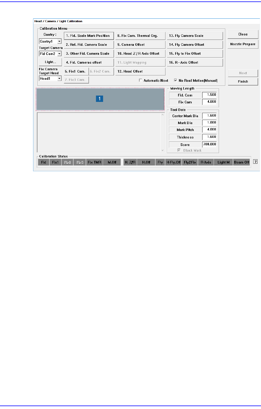
Figure14.12 “Head/ Camera/ Light Calibration” dialog box
1: Head/ Camera/ Light Calibration” dialog box
<Calibration Menu> group
Select an item to be calibrated. If you click the button of a specific item, the
description on the works to be performed are displayed in the message box in order.
Follow the instructions to complete the calibration.
<Gantry> combo box
Select the Gantry for performing Calibration
<Target Camera> combo box
Select the camera to set light value.
<Light…> button
Set the light value for the selected camera.
14-44
Next Generation, Multi-Functional Placer DECAN S1 Administrator’s Guide
14.3.8.1. Fix Camera Calibration (Scale & Rotation & Position)
Calibrate the Scale (um/pixel), Rotation (deg) and Position (mm) of the Fix Camera. In
order to calibrate the Fix Camera, a dedicated fiducial mark jig must be used. (CNT20
Nozzle)
Perform calibration of the Fix Camera in the following manner:
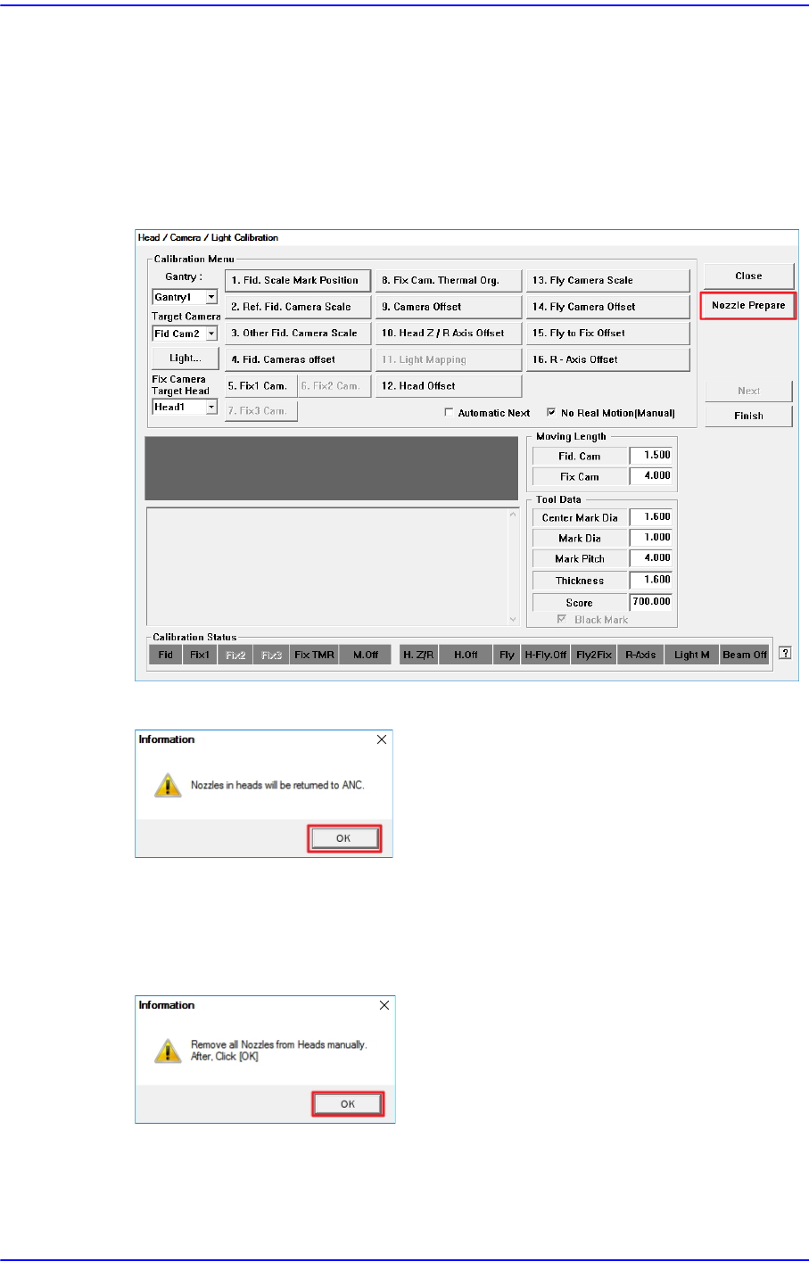
1. Click the <Nozzle Prepare> button.
2. Click the <OK> button.
3. Click the <Next> button to move down the Z axis of the head in order to remove all
nozzles inserted in the nozzle-holder manually.
Then, after the head assembly moves to the designated position, move all Z-axes
down. At this time, remove all inserted nozzles manually