DECAN_S1_Administrator′s_Guide(Eng_Ver1.5)_Print.pdf - 第188页
7-24 Next Generation, Multi-Functional Plac er DECAN S1 Administrator’s Guide <Emboss> check box Check whethe r the reel type o f the feed er to feed the pa rt being edited is “Emboss”. Whether this check box is …
7-23
Part Registration
However, if the part is long, even though it was placed holding it at the
center, both sides of the long part may contact sufficiently with the PCB.
In this case, this problem can be solved by pressing the part so that both
sides of the part or a certain section of it may contact the PCB.
As such, this function is useful when performing the work by setting the
position corresponding to the section that needs contact on the PCB
without picking up the actual part in order to make the part that was
already placed come into sufficient contact with the PCB.
First, set the placement point by using the specific part that needs such
work, Register the part to which this function is applied and set the
placement point of this part to the position at which the placed part is
pressed. Create as many placement points as needed in this manner.
Then, place the specific part first and make it contact with the PCB using
Virtual Pick.
Caution Using this function may cause serious wear of the nozzle.
We take no responsibility for the occurrence of nozzle wear
due to this function.
<Vacuum Check> check box
Check it to carry out vacuum check during the component pick-up.
Since the micro chip is very small, after it is placed, even though it is not
placed actually, not only is it difficult to detect such error in the post process
but also great effort is needed when placing the part again.
Therefore, if this function is used, the machine remembers the pressure
applied to the part when it was picked up and compares this memorized
pressure to the pressure applied to the part when it is placed finally to check if
there is any variation.
If discrepancy occurs, the part may have been dropped due to a certain reason
while the head moves to the placement point after picking it up.
<Use Compatible Camera> check box
Enables the camera with same FOV as the camera that is designated at the
time of component registration to work for efficient work. For example, in
case the Fix Camera 1 is designated to work, if the FOV is same, it allows the
Fix Camera 2 to work for the work efficiency.
<Barcode> check box
It is possible to enable the feeder list when setting the barcode position. For
more details, refer to “6.6.2. Barcode Position”.

7-24
Next Generation, Multi-Functional Placer DECAN S1 Administrator’s Guide
<Emboss> check box
Check whether the reel type of the feeder to feed the part being edited is
“Emboss”. Whether this check box is ticked depends on whether the “Auto
Apply Pick Up Height” function is applied. For details, refer to “14.4.1.
<Auto Apply Pick Up Height> check box” in the <General> tab dialog box.
7-25
Part Registration
7.1.1. Common Align Data
Provides details concerning the align data commonly applied to all parts.
<Camera No.> combo box
Fly Cam: Selects the fly camera of the head.
Memo The fly camera for recognizing each head is as follows:
Fly Cam1: Head #1~Head #2 of the front gantry
Fly Cam2: Head #3~Head #4 of the front gantry
Fly Cam3: Head #5~Head #6 of the front gantry
Fly Cam4: Head #7~Head #8 of the front gantry
Fly Cam5: Head #9~Head #10 of the front gantry
Fix Cam1: Select the fix camera.
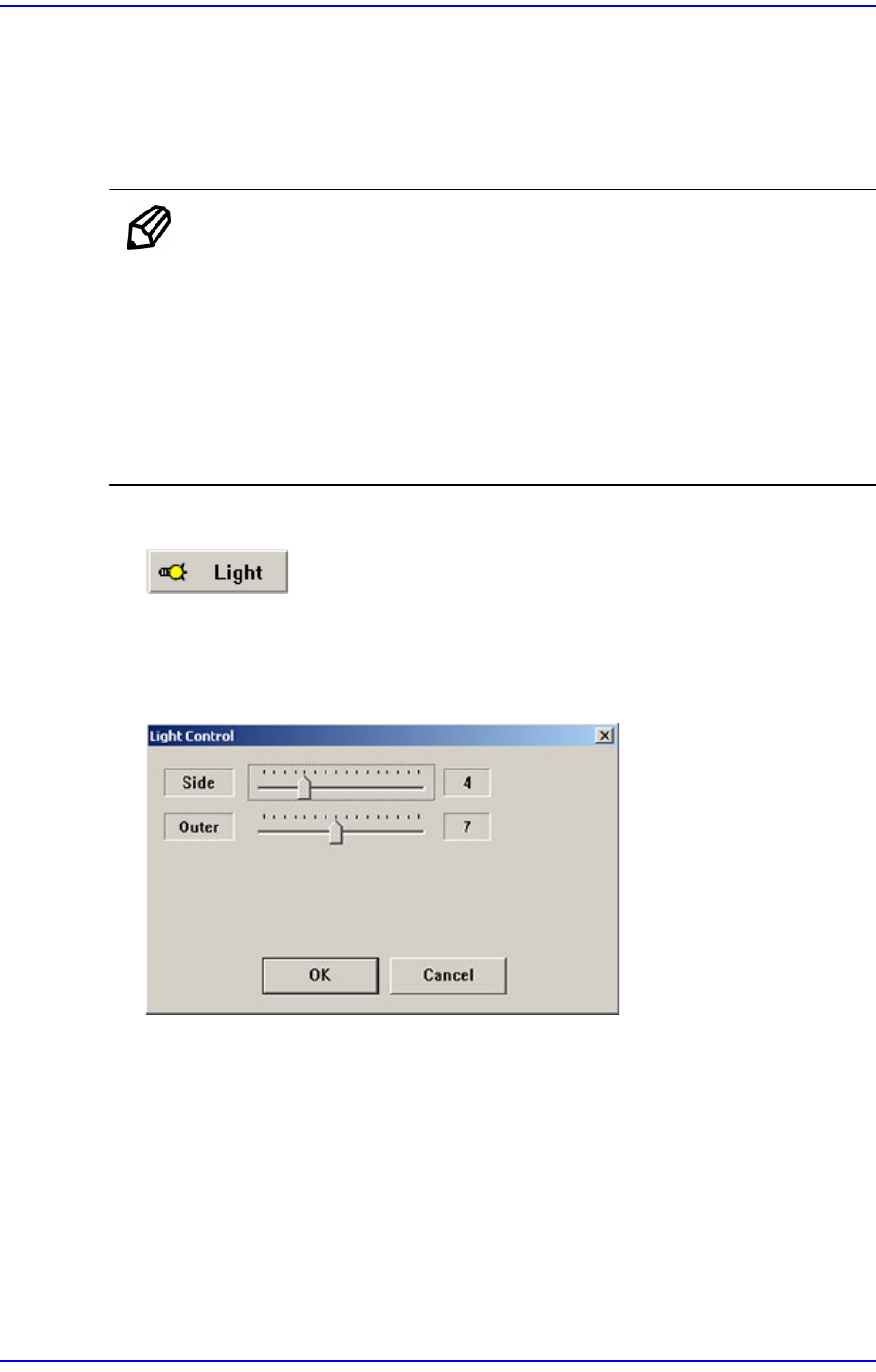
button
Sets the lighting for the camera to recognize the component. When this button is
clicked on, the following dialog box is displayed.
Figure7.7 “Camera No. =Fly Camera“ dialog box