DECAN_S1_Administrator′s_Guide(Eng_Ver1.5)_Print.pdf - 第210页
7-46 Next Generation, Multi-Functional Plac er DECAN S1 Administrator’s Guide Center X Refers to the coordinate in the X dir ection of the Black area based on the part center . (Refers to the figure in the dia log box)…
7-45
Part Registration
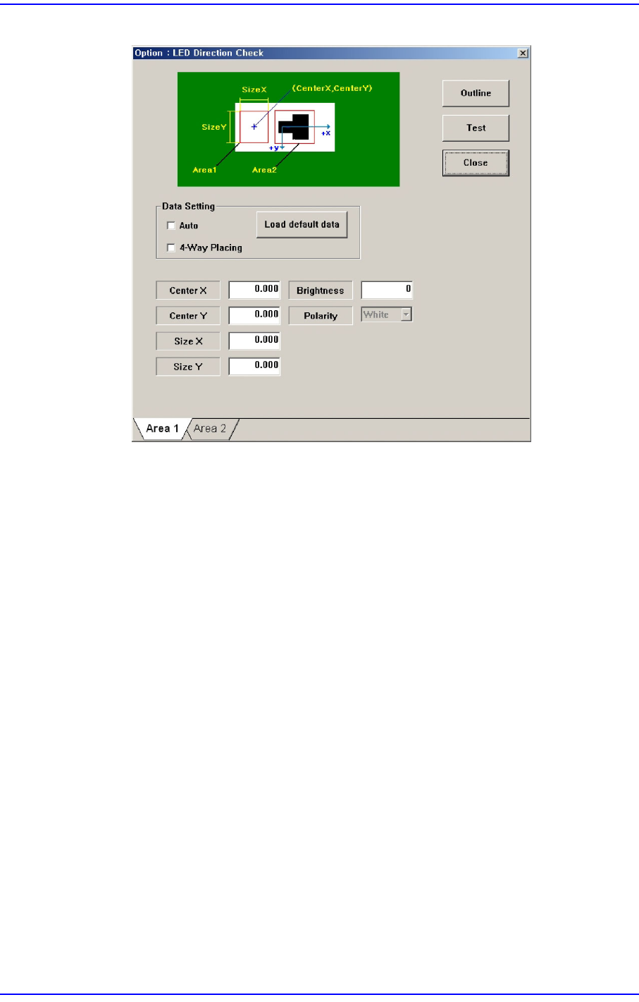
Figure7.14 “LED direction check” check box
Set the White area of the LED in the ‘Area 1’ tab dialog box.
Center X
Refers to the coordinate in the X direction of the White area based on the
part center. (Refers to the figure in the dialog box)
Center Y
Refers to the coordinate in the Y direction of the White area based on the
part center. (Refers to the figure in the dialog box)
Size X
Size of the tetragonal area in the X direction (mm)
Size Y
Size of the tetragonal area in the Y direction (mm)
Brightness
Refers to the reference value of the White area. The White area with a
value less than the reference value can be considered normal. Generally, it
has a value of 200 and above.
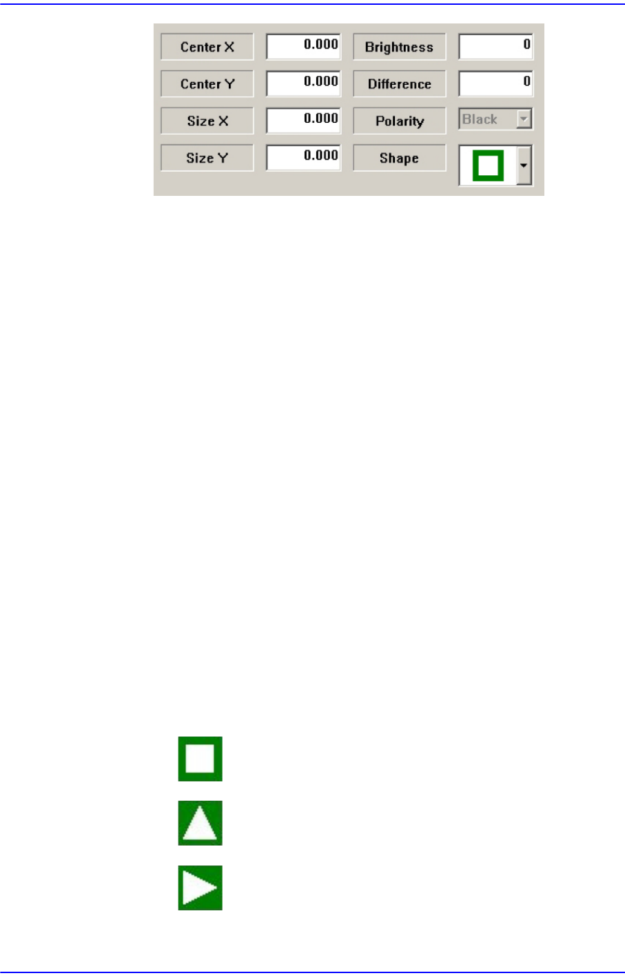
Set the Black area of the LED in the ‘Area 2’ tab dialog box.
7-46
Next Generation, Multi-Functional Placer DECAN S1 Administrator’s Guide
Center X
Refers to the coordinate in the X direction of the Black area based on the
part center. (Refers to the figure in the dialog box)
Center Y
Refers to the coordinate in the Y direction of the Black area based on the
part center. (Refers to the figure in the dialog box)
Size X
Size of the tetragonal area in the X direction (mm)
Size Y
Size of the tetragonal area in the Y direction (mm)
Brightness
Refers to the reference value of the White area. The White area with a
value greater than the reference value can be considered normal.
Difference
Input the minimum difference in the brightness between <Area 1> and
<Area 2>. Generally, input 40.
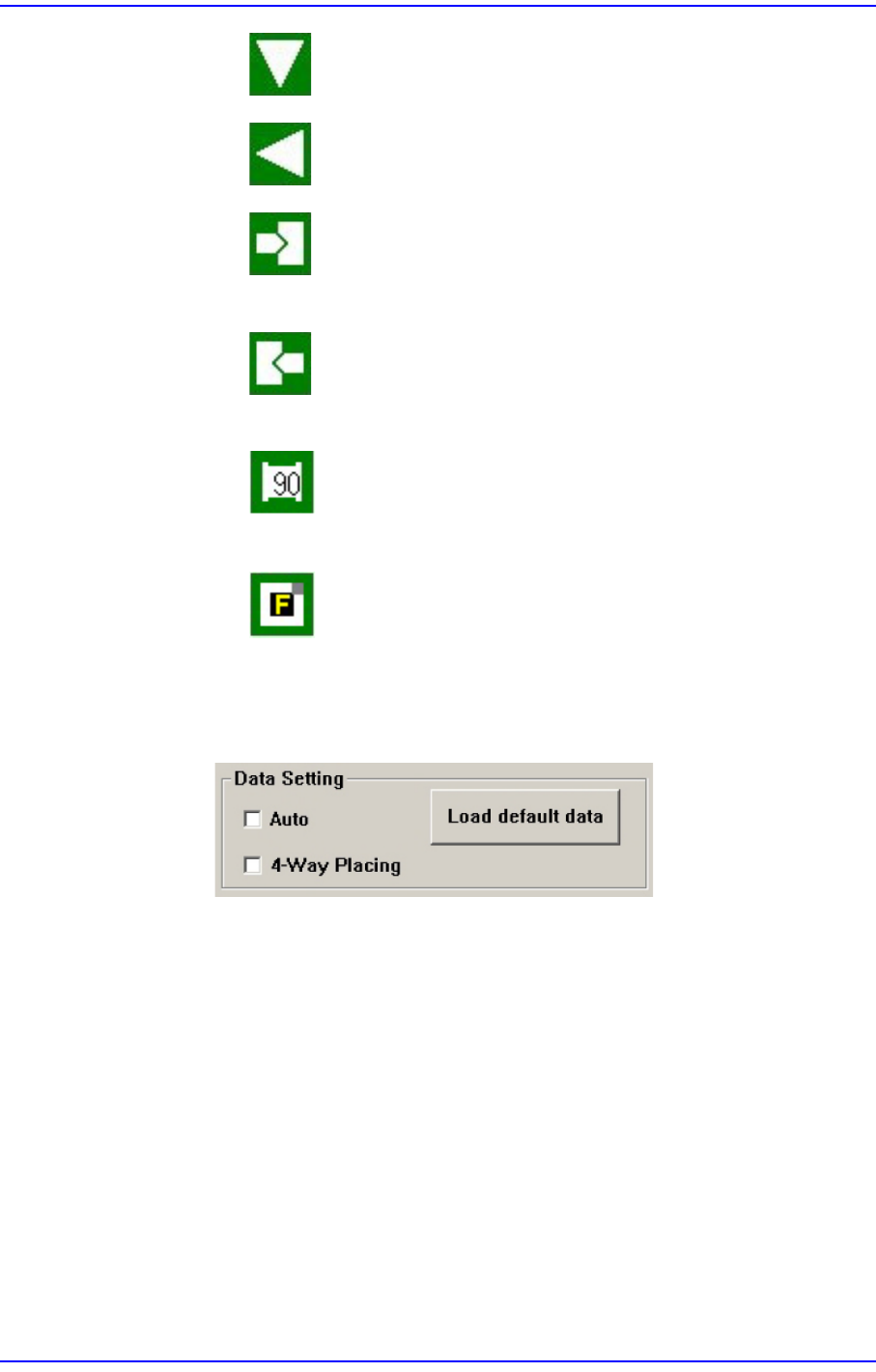
Shape
Select a shape according to the mark or concavo-convex on the bottom surface
of the LED. If the concavo-convex shape is selected, the brightness of the
selected area as well as the direction of a protrusion are checked. This,
therefore, prevents the part from being placed upside down.
: There is no shape.
: Triangle mark in the 0° direction.
: Triangle mark in the 90° direction.
7-47
Part Registration
: Triangle mark in the 180° direction.
: Triangle mark in the 270° direction.
: There is a recess or protrusion at the bottom surface of the part
in the left direction. (concavo-convex)
: There is a recess or protrusion at the bottom surface of the part
in the right direction. (concavo-convex)
: Selected when recognizing the shape of a part rotated by 90
degrees. This is not used currently.
: When performing work by recognizing an FCOM (LED chip) in
4 directions
Select the option function used when recognizing the LED using the vision
system in the <Data Setting> group.
<Auto> check box
When there is a black area on the LED bottom surface (surface to be
recognized by the vision system) without specific marks such as a
tetragon or triangle on it, if this check box is selected, this image is
considered to be one of the images shown below.
<4-Way Placing> check box
When recognizing an LED part, if it was picked up being turned 180°, this
function allows the part to be placed by turning it 180° without dumping
it. Mainly, this function is enabled when using a bowl feeder.
In order to use this function, the characteristics, position and size of the
LED mark must be inputted correctly. When there is a symmetrical mark
on the bottom surface of the part, exercise care not to use this function.