00197187-01_AI_LBO_SX12_ab_09-2011_FS02_de_en.pdf - 第46页
Brief Description Scope of Delivery Parts Overview 46 Long Board Option 1. Cover 2 right sto pper rail LBO SX12 [03091990 - xx] 2. Cover 2 left stopper ra il LBO SX12 [03091991 - xx] 1. Stopper 25 SX pn eumatic complete …
Brief Description
Parts Overview Scope of Delivery
Long Board Option 45
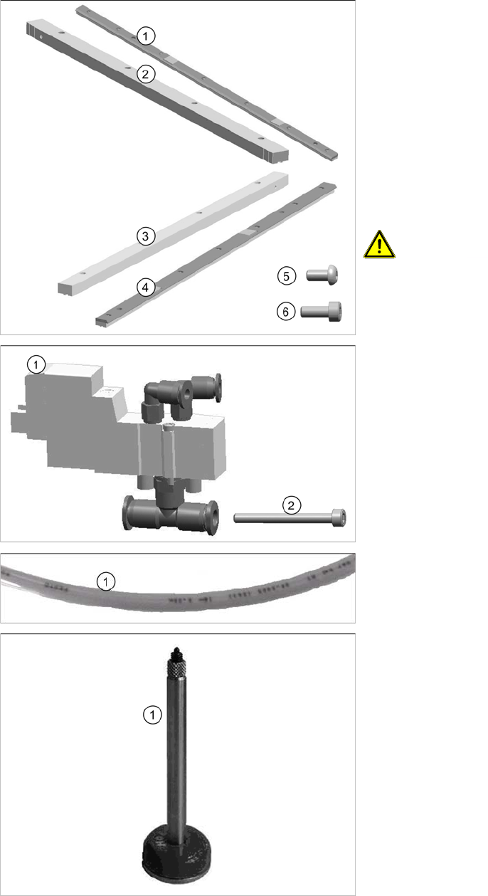
2.2.3 Parts Overview
1. Stop guide rail (right) 599 complete [03088196-xx]
(incl. 7 screws (5))
2. Guidance rail AB R [03088180-xx]
3. Guidance rail AB L [03088179-xx]
4. Stop guide rail (left) 599 complete [03088191-xx]
(incl. 7 screws (5))
5. Filister hex socket head screw for fitting the stop
guide rail (DIN-EN-ISO7380-M3x6-12.9)
[00200240-xx] (7x per stop guide rail)
6. Socket head cap screw for fitting the guidance rail to
the side (ISO4762-M3x8-A2-70)
CAUTION!
Make sure you only use the filister hex socket head screw
when fitting the stop guide rails to the guidance rails. Any
other screws could cause a head crash!
1. Valve unit stopper assembly [03084466-xx] (incl. 2
screws (2))
2. 2x socket head cap screw for fitting the valve
(ISO4762-M1.6x16-A2-70) [03042521-xx]
1. Compressed-air hose PUN-3x0.5-BL [03053429-xx]
1. Spring-mounted PCB support 94 mm [03082256-xx]
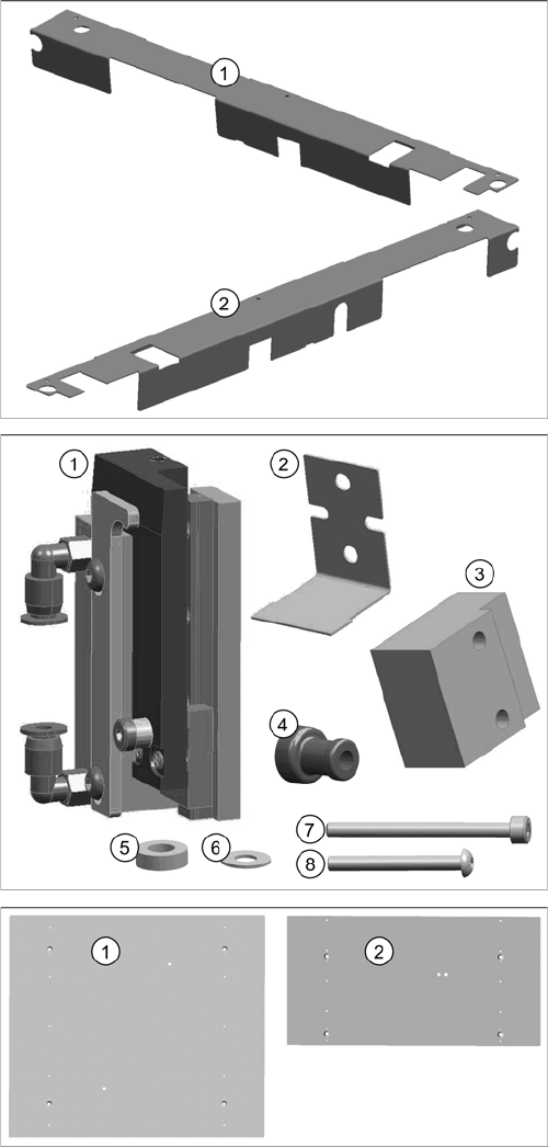
Brief Description
Scope of Delivery Parts Overview
46 Long Board Option
1. Cover 2 right stopper rail LBO SX12 [03091990-xx]
2. Cover 2 left stopper rail LBO SX12 [03091991-xx]
1. Stopper 25 SX pneumatic complete [03084034-xx]
2. Sheet [03084255-xx]
3. Spacer LBO [03091992-xx]
4. Support socket [03085311-xx]
5. Distance washer M3 / H=2 mm [03092259-xx]
6. Washer (H = 0.5 mm, DIN125-A-3.2-140HV-A2)
[00316904-xx]
7. Socket head cap screw for fitting the stopper
(ISO4762-M3x35-A2-70) [03043114-xx]
8. Filister hex socket head screw for fitting the stopper
(DIN-EN-ISO7380-M3x25-A2-70) [03045198-xx]
1. Lifting table plate LBO B2 SC (Single Conveyor)
[03070780-xx]
2. Lifting table plate LBO B2 DC (Double Conveyor)
[03070791-xx]
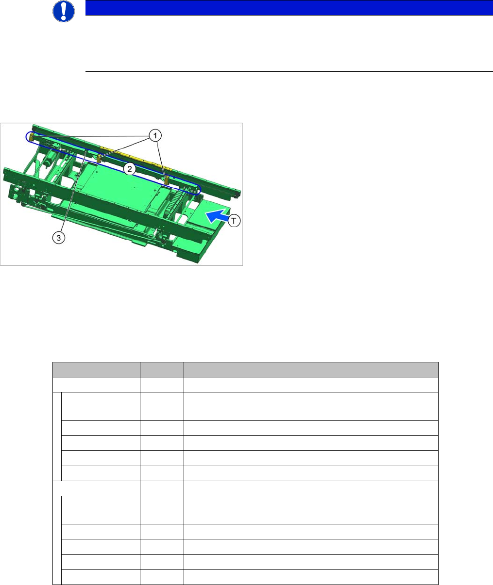
Fitting the Long Board Option
Overview
Long Board Option 47
3 Fitting the Long Board Option
3.1 Overview
3.2 Preparing the Stop Guide Rails
Overview of stop guide rail parts
NOTICE
Single conveyor
Installation of the option is described below, using the example of a dual conveyor. Unless oth-
erwise specified, installation for a single conveyor is identical to that described for lane 1 of the
dual conveyor.
Overview of single conveyor SX1/SX2 (FS02)
1. Standard stopper
2. Sensor rail
3. Installation position of new stopper
T = transport direction
Item No. Quantity Designation
03088191-xx Stop guide rail left 599 complete
00200240-xx 7 Filister hex socket head screw (DIN-EN-ISO7380-M3x6-
12.9)
03064824-xx 2 Spring steel plate for height reference run
00317829-xx 2 Positioning fiducial
03088194-xx 1 Stop guide rail with rubber molding left 599
03088192-xx 1 Guidance rail left 599 (lower section)
03088196-xx Stop guide rail right 599 complete
00200240-xx 7 Filister hex socket head screw (DIN-EN-ISO7380-M3x6-
12.9)
03064824-xx 2 Spring steel plate for height reference run
00317829-xx 2 Positioning fiducial
03088199-xx 1 Stop guide rail with rubber molding right 599
03088197-xx 1 Guidance rail right 599 (lower section)