00197187-01_AI_LBO_SX12_ab_09-2011_FS02_de_en.pdf - 第58页
Fitting the Long Board Option Final Wo rk 58 Long Board Option The installation is now complete . See also 4.1 Settin g the Paralle lism and Height of the Lifting Table Pla te [ ➙ 59] 4.3 Lo osening th e Conveyo r S …
Fitting the Long Board Option
Final Work
Long Board Option 57
3.8 Final Work
► Fasten any loose cables with cable ties, where required.
► Repeat the entire conversion procedure on lane 2 of the dual conveyor, if used.
► Fit the new cover sheets onto the sensor rails.
- cover 2 right stopper rail LBO SX12 [03091990-xx]
- cover 2 left stopper rail LBO SX12 [03091991-xx]
► Switch on the machine
► Calibrate the lifting table motors. (See Calibrating the Lifting Table Motors in SX1/2 Conveyors)
The lifting table motors need to be calibrated due to the weight of the new lifting table plates.
► Perform a stopper test.
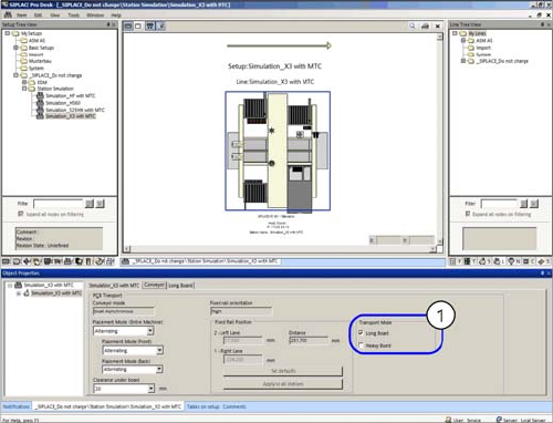
Enabling the LB option
CAUTION
Take care not to damage the cables.
► Always make sure that the cables do not rub against any parts, are not pinched or folded.
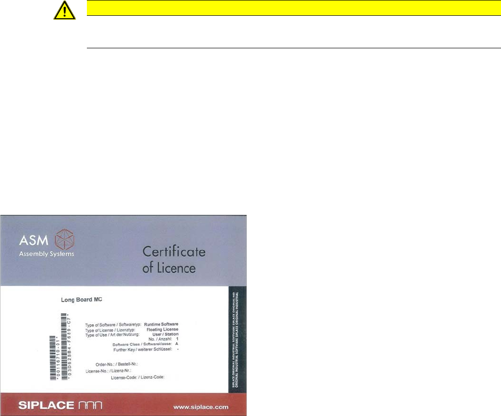
► Enable the license for this option on the SIPLACE-
PRO line computer. The license key can be obtained
from the ASM-AS internet license portal, using the
"Long Board MC" [00116710-01] certificate provided.
If you should have any questions about the license,
contact your SIPLACE Service team.
Annex
Setting the Parallelism and Height of the Lifting Table Plate
Long Board Option 59
4 Annex
4.1 Setting the Parallelism and Height of the Lifting Table Plate
Parts, equipment and tools
▪ Depth measuring gauge (200 mm) [03079617-xx]
Setting
► Initialize or move the lifting table before performing measurement. This is important as the bottom
position is not automatically the mechanical end position. Move the lifting table to the bottom stopper:
Check sensors and functions --> Check sensors and functions of specific
components --> Conveyor – inputs/outputs --> Lane --> Lifting table down.
To achieve a position which can be reproduced, it may be advisable to move the lifting table once
from the central position downwards. (Not multiple times downwards when it is already in the bottom
position.)
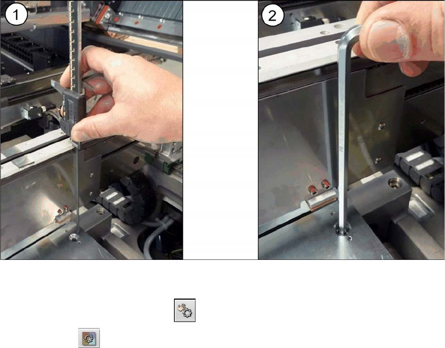
► (1) Use the measuring gauge to measure the distance from the top edge of the conveyor to the top
edge of the lifting table plate.
► (2) Set the height of the lifting table plate with the help of the plate guides to 145 -0.2 mm. You do
not need to remove the lifting table plate for this as the hexagon socket-head screws on the plate
guides can be reached with an Allen key size 6, through the holes provided in the lifting table plate.
However, the lifting table plate will need to be screwed tight again before you perform measurement.
► Perform this measurement procedure at all four screws fastening each lifting table plate. This is es-
sential for guaranteeing the parallelism of the lifting table plates. The four measurements may not
deviate from one another by more than 0.1 mm.
► Calibrate the zero position of the lifting table motor.