00197187-01_AI_LBO_SX12_ab_09-2011_FS02_de_en.pdf - 第53页
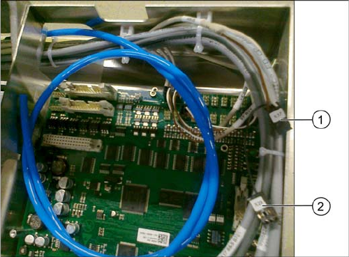
Fitting the Long Board Option Fitting the Valve Unit Long Board Option 53 Connecting the valve unit to the TSP400 ► Connect the cables to the TSP400 with the connec - tors X37 (1) and X29 (2) . This cab le h as been pre-…
Fitting the Long Board Option
Fitting the Valve Unit
52 Long Board Option
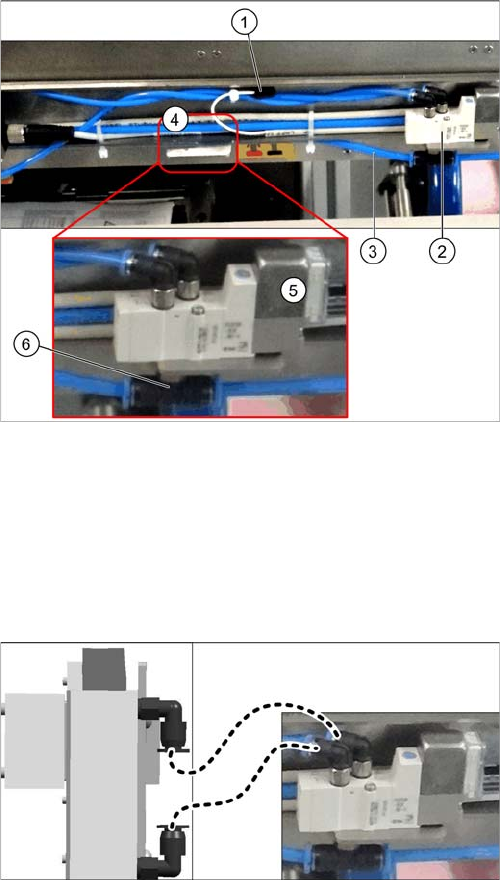
3.5 Fitting the Valve Unit
Overview
Fitting the valve unit
► Use the two fastening screws to fit the valve unit in its installation position (4).
► Plug the connection cable (1) into the valve unit.
► Sever the compressed air supply hose (3) at the height of the T-piece (6) of the new valve unit. To
do this, loosen the relevant cable ties. Connect both ends of the severed hose to the T-piece.
► Run all hoses so that they do not rub against anything and are not folded. Fasten them into place
with cable ties.
1. Connection cable for valve unit
2. Neighboring valve unit
3. Compressed air supply hose
4. Installation position for valve unit
5. Valve unit when fitted
6. T-piece on the valve unit
► Connect the left connection on the valve to the lower
connection on the stopper.
► Connect the right connection on the valve to the up-
per connection on the stopper.
Fitting the Long Board Option
Fitting the Valve Unit
Long Board Option 53
Connecting the valve unit to the TSP400
► Connect the cables to the TSP400 with the connec-
tors X37 (1) and X29 (2). This cable has been pre-run
and is already in the conveyor.
For an overview of connectors for TSP400, see section
"4.4 Conveyor Control TSP 400" [ ➙ 62].
Fitting the Long Board Option
Replacing the Lifting Table Plates
54 Long Board Option
3.6 Replacing the Lifting Table Plates
► Move the conveyor system to the maximum possible width.
► Loosen the screws fastening the two lifting table plates (4 x for each lifting table plate) and remove
the lifting table plates from the machine.
► Mark the positions of the lifting table plate fixtures to make it easier to refit them later on. Make sure
you do not confuse these.
► Now place the new (larger) lifting table plate onto the plate guidance.
► Fit the lifting table plate into place with the fastening screws. Adjust the edges to ensure that they
are parallel to the lifting table plate. (See "4.1 Setting the Parallelism and Height of the Lifting Table
Plate" [ ➙ 59])
► Dual conveyor: if the conveyor side clamps have been loosened, fix these again. Make sure that
the side edges are parallel.
CAUTION
Heavy machine part!
When removing the lifting table plates, remember that they are heavy. You may need to enlist
the help of a second person.
NOTICE
Single and dual conveyor
There is one lifting table plate in the single conveyor and two in the dual conveyor. Replacement
is described below, using the example of the single conveyor. For replacement in a dual con-
veyor, simple repeat the same steps for the second lifting table plate.
NOTICE
Move out conveyor sides, loosen clamps
Moving the conveyor sides to the maximum possible width is normally enough to allow room for
removing the lifting table plate from the conveyor.
In dual conveyors, you can also loosen the clamps for the relevant conveyor sides. These sides
can then be moved.
► (See section"4.3 Loosening the Conveyor Side Clamps (DT only)" [ ➙ 60].)
NOTICE
Single conveyor
The conveyor side clamps can only be loosened for dual conveyors. This is not possible for sin-
gle conveyors.
The flexible side of single conveyors can be moved when the machine is switched off, by care-
fully pulling on the width adjustment belt.