00197187-01_AI_LBO_SX12_ab_09-2011_FS02_de_en.pdf - 第62页
Annex Conveyor Control TS P 400 TSP400 Overview 62 Long Board Option 4.4 Conveyor Control TSP 400 4.4.1 TSP400 Overview (1) DI P switch S3 (2) Button S1 and S2 (3) L EDs H1 to H4 (4) Connectors X7, X8, X14, X19 and X40 (…
Annex
Loosening the Conveyor Side Clamps (DT only)
Long Board Option 61
Restoring the clamp
► Follow the removal instructions in reverse order for installation. Also observe the following instruc-
tions:
Version 1
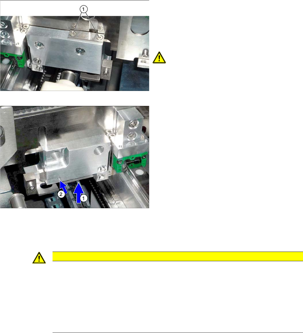
► Loosen the clamps on the conveyor sides.
To do this, remove the disks above the clamp com-
pression springs (2 screws for each disk). To do this,
loosen both screws (1) on the clamps (2 x for each
conveyor side).
CAUTION!
Compression springs
The compression springs are tensioned.
Make sure that you do not lose these.
You can now move the sides.
Version 2
► Loosen the conveyor side clamps. To do this, press
the lever (1) upwards and push a suitable pin into the
hole (2).
► Repeat these steps for all clamps on the sides con-
cerned.
You can now move the sides.
CAUTION
Installation instructions
► Make sure that the conveyor sides are aligned parallel again. You may need to push these
up to the stop on one side to check.
► Use a board to test the parallelism. This board must be transported evenly through the en-
tire conveyor.
► Make sure that the conveyor sides are back in their original positions after switching on.
Perform a complete reference run to check this. (This is performed automatically when you
start up the machine again.)
Annex
Conveyor Control TSP 400 TSP400 Overview
62 Long Board Option
4.4 Conveyor Control TSP 400
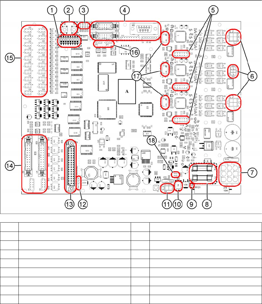
4.4.1 TSP400 Overview
(1) DIP switch S3 (2) Button S1 and S2
(3) LEDs H1 to H4 (4) Connectors X7, X8, X14, X19 and X40
(5) Connectors X15 to X17 (6) Connectors X10 to X12
(7) Connector X5 (8) Fuses F1 and F2
(9) LED H7 (10) Fuse F3
(11) Connector X18 (12) Jumper JP3
(13) Connector X9 (14) Connectors X1 and X2
(15) Connectors X20 to X39 (16) Jumpers JP1 and JP2
(17) Potentiometers P1 to P3 (18) LED H5 and H6

Annex
TSP400 Connector Conveyor Control TSP 400
Long Board Option 63
4.4.2 TSP400 Connector
4.4.3 TSP400 Fuses
4.4.4 TSP400 Potentiometer
4.4.5 TSP400 Switches and Buttons
X1 Siemens interface, predecessor station X21 Board sensor placement area
X2 Siemens interface, successor station X22 Spare
X3 SMEMA interface, predecessor station X23 Board sensor output area
X4 SMEMA interface, successor station X24 Sensor conveyor side width adjustment
unit 1
X5 Power supply X25 Sensor conveyor side width adjustment
unit 2
X26 Sensor cylinder width adjustment unit 1
X7 CAN bus to machine controller X27 Sensor cylinder width adjustment unit 2
X8 V24 interface for troubleshooting (debug) X28 Spare
X9 Interface to board TSP400E (optional) X29 Stopper Long Board Option coding (togeth-
er with X37)
X10 Motor for conveyor X30 Spare
X11 Width adjustment motor X31 Spare
X12 Motor for lifting table X32 Pneumatic valve width adjustment unit 1
X33 Pneumatic valve width adjustment unit 2
X14 CAN bus to conveyor lane X34 Spare
X15 Track signals for conveyor motor X35 Stopper for input area
X16 Track signals for width adjustment motor X36 Stopper for placement area
X17 Track signals for lifting table motor X37 Stopper Long Board Option (together with
X29)
X18 Brake for lifting table X38 Stopper for output area
X19 Programming interface for development X39 Spare
X20 Board sensor input area X40 Programming interface for development
F1 [03079942-xx] Microfuse 5x20 /
T 2A / ceramic
T2A Fuse protection
24V
(sensors, control system supply)
F2 [03078843-xx] Microfuse 5x20 /
T 6.3A / ceramic
T6.3A Fuse protection
40V
(supply to drives)
F3 Self-restoring SMD fuse Polyswitch set for 24 V (supply to lifting table brake), not
replaceable
G1 Setting the zero point of the control loop for the lifting table/conveyor belt/width adjustment motor
(needs to be performed only once
G2 by the manufacturer and is then sealed with locking varnish). The potentiometer will be dis-
pensed with in future
G3 and replaced with an eSW teach function.
S1 Reset XC167 (used for eSW development only)
S2 Reset XC167 (used for eSW development only)
S3 Configuration for single and dual conveyor