00197187-01_AI_LBO_SX12_ab_09-2011_FS02_de_en.pdf - 第52页
Fitting the Long Board Option Fitting the Valve Unit 52 Long Board Option 3.5 Fitting the Valve Unit Overview Fitting the valve unit ► Use the two fastening screws to fit the valve un it in its insta llation position (4)…
Fitting the Long Board Option
Installing the Stopper
Long Board Option 51
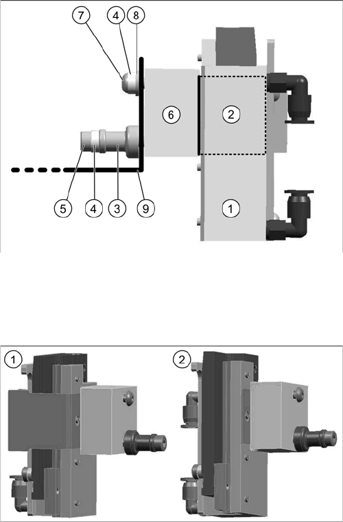
Fitting the stopper
► Dismantle the cover sheet over the installation position on the sensor rail.
► Fit the individual parts of the stopper to the mounting bracket on the stopper rail, as shown in the
diagram above. Make sure that the sheet is positioned correctly [03084255-xx] (left or right).
Fitting the complete stopper assembly (right shown here)
1. Stopper 25 SX pneumatic complete [03084034-xx]
2. Sheet [03084255-xx] ("right" position shown here)
3. Support socket [03085311-xx]
4. Distance washer M3/H=2 mm [03092259-xx]
5. ISO4762-M3x35-A2-70 socket head cap screw for fit-
ting the stopper [03043114-xx]
6. Spacer LBO [03091992-xx]
7. DIN-EN-ISO7380-M3x25-A2-70 - filister hex socket
head screw [03045198-xx]
8. DIN125-A3,2-140HV-A2 - washer 0.5 mm high
[00316904-xx]
9. Mounting bracket on the sensor rail
1. Stopper with sheet in "left" position for fitting onto the
right conveyor side
2. Stopper with sheet in "right" position for fitting to the
left conveyor side (DT "lane" 2)
Fitting the Long Board Option
Fitting the Valve Unit
52 Long Board Option
3.5 Fitting the Valve Unit
Overview
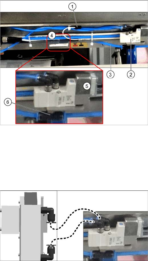
Fitting the valve unit
► Use the two fastening screws to fit the valve unit in its installation position (4).
► Plug the connection cable (1) into the valve unit.
► Sever the compressed air supply hose (3) at the height of the T-piece (6) of the new valve unit. To
do this, loosen the relevant cable ties. Connect both ends of the severed hose to the T-piece.
► Run all hoses so that they do not rub against anything and are not folded. Fasten them into place
with cable ties.
1. Connection cable for valve unit
2. Neighboring valve unit
3. Compressed air supply hose
4. Installation position for valve unit
5. Valve unit when fitted
6. T-piece on the valve unit
► Connect the left connection on the valve to the lower
connection on the stopper.
► Connect the right connection on the valve to the up-
per connection on the stopper.
Fitting the Long Board Option
Fitting the Valve Unit
Long Board Option 53
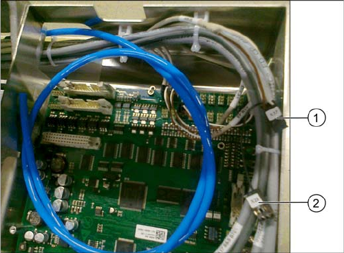
Connecting the valve unit to the TSP400
► Connect the cables to the TSP400 with the connec-
tors X37 (1) and X29 (2). This cable has been pre-run
and is already in the conveyor.
For an overview of connectors for TSP400, see section
"4.4 Conveyor Control TSP 400" [ ➙ 62].