00197187-01_AI_LBO_SX12_ab_09-2011_FS02_de_en.pdf - 第59页
Annex Setting the Parallelism and Hei ght of the Lifting Table Pla te Long Board Option 59 4 Annex 4.1 Setting the Parallelism and Height of the Lifting Table Plat e Parts, equipment and tools ▪ Depth measuring gauge (20…
Annex
Setting the Parallelism and Height of the Lifting Table Plate
Long Board Option 59
4 Annex
4.1 Setting the Parallelism and Height of the Lifting Table Plate
Parts, equipment and tools
▪ Depth measuring gauge (200 mm) [03079617-xx]
Setting
► Initialize or move the lifting table before performing measurement. This is important as the bottom
position is not automatically the mechanical end position. Move the lifting table to the bottom stopper:
Check sensors and functions --> Check sensors and functions of specific
components --> Conveyor – inputs/outputs --> Lane --> Lifting table down.
To achieve a position which can be reproduced, it may be advisable to move the lifting table once
from the central position downwards. (Not multiple times downwards when it is already in the bottom
position.)
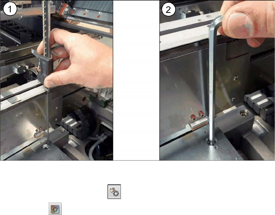
► (1) Use the measuring gauge to measure the distance from the top edge of the conveyor to the top
edge of the lifting table plate.
► (2) Set the height of the lifting table plate with the help of the plate guides to 145 -0.2 mm. You do
not need to remove the lifting table plate for this as the hexagon socket-head screws on the plate
guides can be reached with an Allen key size 6, through the holes provided in the lifting table plate.
However, the lifting table plate will need to be screwed tight again before you perform measurement.
► Perform this measurement procedure at all four screws fastening each lifting table plate. This is es-
sential for guaranteeing the parallelism of the lifting table plates. The four measurements may not
deviate from one another by more than 0.1 mm.
► Calibrate the zero position of the lifting table motor.
Annex
Calibrating the Lifting Table Motors in SX1/2 Conveyors
60 Long Board Option
4.2 Calibrating the Lifting Table Motors in SX1/2 Conveyors
Due to the higher weight of the lifting table plates for the LBO, you need to recalibrate the lifting table
motor.
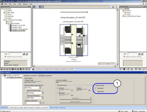
► Start up the station.
► Switch over to the activity level Machine Service (or better still)
► Switch over to the service menu .
► Select the Conveyor configuration button.
4.3 Loosening the Conveyor Side Clamps (DT only)
Many tasks performed on the conveyor require that the conveyor sides are moved when the machine is
switched off. The conveyor side clamps on the dual/quad conveyor can be released for this purpose.
Parts, equipment and tools
▪ Per side:
3x ISO4762-M3x35-A2-70 [03043114-xx] or
3x ISO8734-3x30-A-ST [03015760-xx]
Procedure
► Move the conveyor sides to a position which gives you good access to the clamps.
► Switch off the machine, disconnect it from the power supply and secure it to prevent unauthorized
reactivation. Observe the instructions in section "1.2 Preparatory Work..." [ ➙ 37].
Select the applicable version of the clamp:
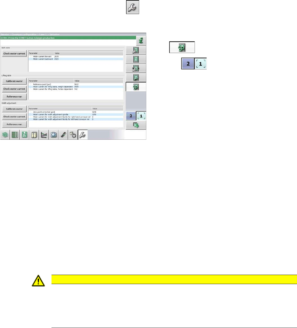
► Select the Initiate conveyor parameters but-
ton .
► Use the button to select the required con-
veyor lane.
► Calibrate the lifting table motor in the Lifting ta-
ble section, by selecting the Motor calibration
button.
CAUTION
Marking the starting positions
After completing this task, move the conveyor sides back to their approximate starting posi-
tions.
► To enable you to find the starting positions later on, you may want to mark the current po-
sitions of the conveyor sides.