00197187-01_AI_LBO_SX12_ab_09-2011_FS02_de_en.pdf - 第61页
Annex Loosening the Conveyor S ide Clamps (DT only) Long Board Option 61 Restoring the clamp ► Follow the removal in structions in reverse order for installati o n. Also observe the following instruc - tions: Version 1 ►…
Annex
Calibrating the Lifting Table Motors in SX1/2 Conveyors
60 Long Board Option
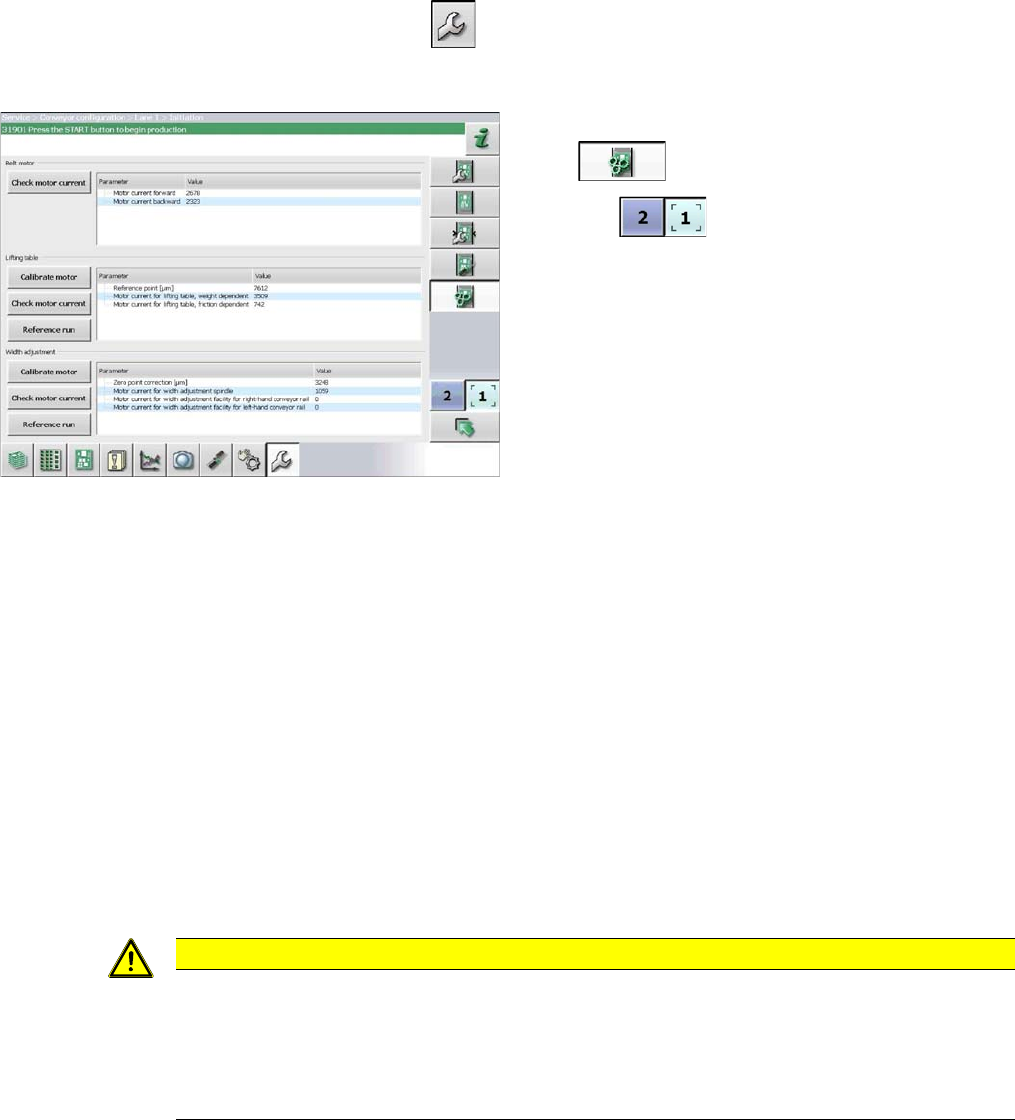
4.2 Calibrating the Lifting Table Motors in SX1/2 Conveyors
Due to the higher weight of the lifting table plates for the LBO, you need to recalibrate the lifting table
motor.
► Start up the station.
► Switch over to the activity level Machine Service (or better still)
► Switch over to the service menu .
► Select the Conveyor configuration button.
4.3 Loosening the Conveyor Side Clamps (DT only)
Many tasks performed on the conveyor require that the conveyor sides are moved when the machine is
switched off. The conveyor side clamps on the dual/quad conveyor can be released for this purpose.
Parts, equipment and tools
▪ Per side:
3x ISO4762-M3x35-A2-70 [03043114-xx] or
3x ISO8734-3x30-A-ST [03015760-xx]
Procedure
► Move the conveyor sides to a position which gives you good access to the clamps.
► Switch off the machine, disconnect it from the power supply and secure it to prevent unauthorized
reactivation. Observe the instructions in section "1.2 Preparatory Work..." [ ➙ 37].
Select the applicable version of the clamp:
► Select the Initiate conveyor parameters but-
ton .
► Use the button to select the required con-
veyor lane.
► Calibrate the lifting table motor in the Lifting ta-
ble section, by selecting the Motor calibration
button.
CAUTION
Marking the starting positions
After completing this task, move the conveyor sides back to their approximate starting posi-
tions.
► To enable you to find the starting positions later on, you may want to mark the current po-
sitions of the conveyor sides.
Annex
Loosening the Conveyor Side Clamps (DT only)
Long Board Option 61
Restoring the clamp
► Follow the removal instructions in reverse order for installation. Also observe the following instruc-
tions:
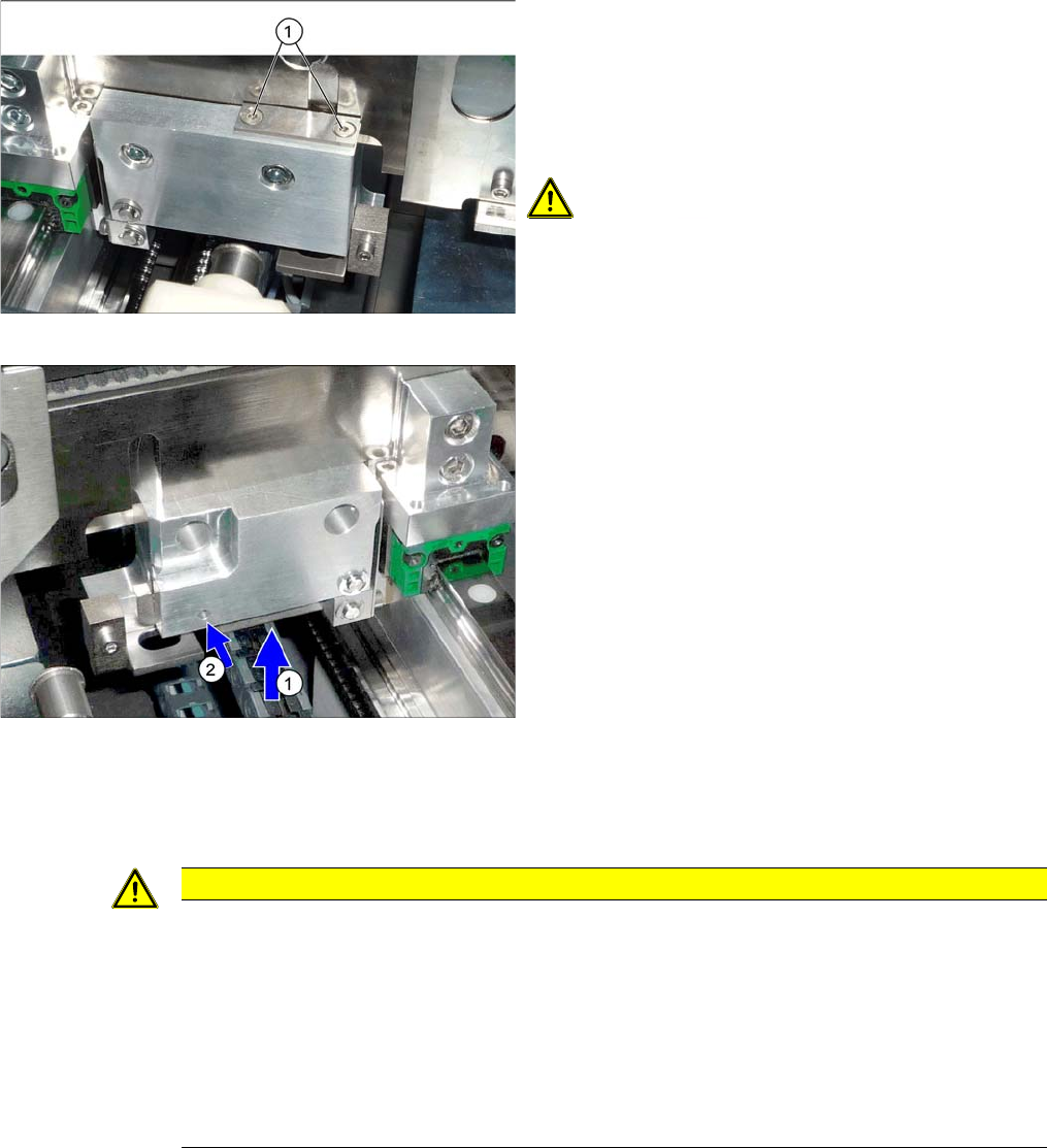
Version 1
► Loosen the clamps on the conveyor sides.
To do this, remove the disks above the clamp com-
pression springs (2 screws for each disk). To do this,
loosen both screws (1) on the clamps (2 x for each
conveyor side).
CAUTION!
Compression springs
The compression springs are tensioned.
Make sure that you do not lose these.
You can now move the sides.
Version 2
► Loosen the conveyor side clamps. To do this, press
the lever (1) upwards and push a suitable pin into the
hole (2).
► Repeat these steps for all clamps on the sides con-
cerned.
You can now move the sides.
CAUTION
Installation instructions
► Make sure that the conveyor sides are aligned parallel again. You may need to push these
up to the stop on one side to check.
► Use a board to test the parallelism. This board must be transported evenly through the en-
tire conveyor.
► Make sure that the conveyor sides are back in their original positions after switching on.
Perform a complete reference run to check this. (This is performed automatically when you
start up the machine again.)
Annex
Conveyor Control TSP 400 TSP400 Overview
62 Long Board Option
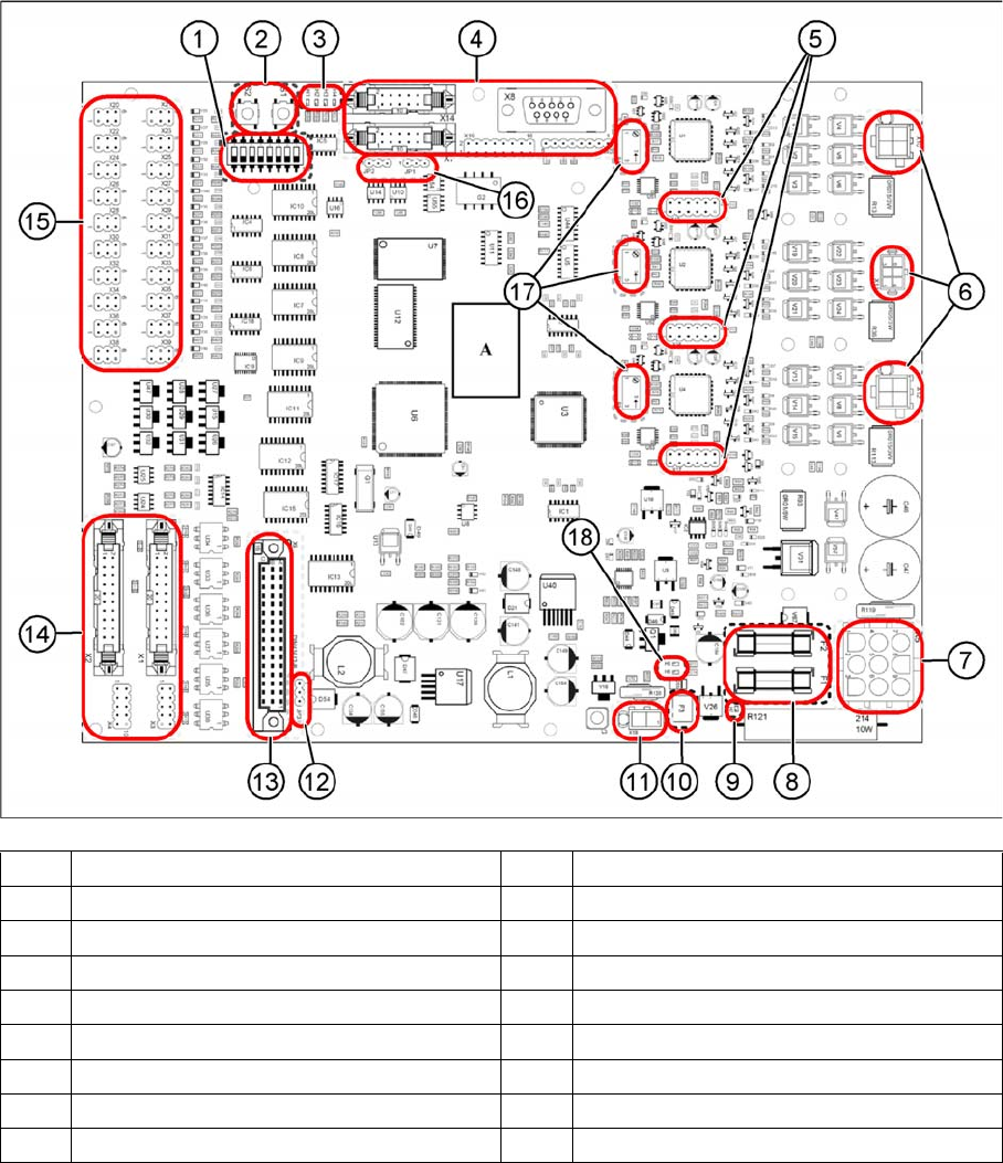
4.4 Conveyor Control TSP 400
4.4.1 TSP400 Overview
(1) DIP switch S3 (2) Button S1 and S2
(3) LEDs H1 to H4 (4) Connectors X7, X8, X14, X19 and X40
(5) Connectors X15 to X17 (6) Connectors X10 to X12
(7) Connector X5 (8) Fuses F1 and F2
(9) LED H7 (10) Fuse F3
(11) Connector X18 (12) Jumper JP3
(13) Connector X9 (14) Connectors X1 and X2
(15) Connectors X20 to X39 (16) Jumpers JP1 and JP2
(17) Potentiometers P1 to P3 (18) LED H5 and H6