00197187-01_AI_LBO_SX12_ab_09-2011_FS02_de_en.pdf - 第56页
Fitting the Long Board Option PCB Support 56 Long Board Option ► Position the required PCB supp orts in the front area of the lif ting table plate. The shorter PCB supports are eac h in the vicinit y of the c onvey or si…
Fitting the Long Board Option
PCB Support
Long Board Option 55
3.7 PCB Support
When using the Long Board Option, the board inserted between the standard stopper position and the
LBO stopper position cannot be clamped along a length of approx. 60 mm. The use of a longer lifting
table plate provides support from below but there is still no clamping edge above, on the conveyor edge.
Special support pins are therefore required in this area.
Overview
Installing the PCB supports
► The required length of the PCB support depends on the expected warpage of the boards to be proc-
essed. Adjust the PCB supports so that any board warpage can be replicated. Position the pins (with-
out magnet protective disk) on a smooth surface and adjust the length with a caliper gauge.
► Begin with 2 PCB supports and set them to a total length of 94.2mm.
► Set the other PCB supports according to the expected warpage.
The length of the other PCB supports needs to be set according to the expected warpage of the
boards. (e.g.: 2x94.5 mm, 2x94.8 mm, 2x95.2 mm, etc.)
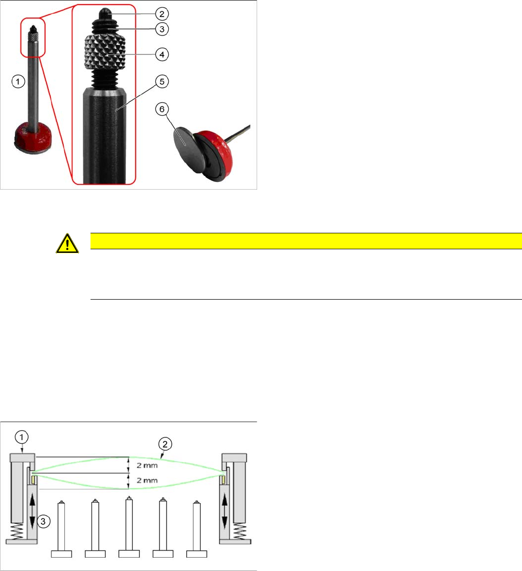
1. Spring-mounted PCB support 94 mm [03082256-xx]
2. Spring-mounted pin
3. Compression spring
This can be screwed into the compression spring
support with the M5 thread to adjust the overall length
of the PCB support. The spring force is 3 N (start) to
10 N (end).
4. Sleeve
This is used as a counter nut, to fix the compression
spring screwed in.
5. Compression spring support
6. Metal disk for protecting the magnets
This needs to be removed before use in the machine.
CAUTION
Remove the metal disk
Make sure that a metal disk is fitted to the underside of the PCB support, to protect the magnet.
► This metal disk needs to be removed before use in the machine!
1. Fixed clamping edge
2. Board
3. Flexible clamping device
Fitting the Long Board Option
PCB Support
56 Long Board Option
► Position the required PCB supports in the front area of the lifting table plate.
The shorter PCB supports are each in the vicinity of the conveyor sides.
The longer PCB supports are to be positioned exactly in the centre, between the two conveyor sides,
so that any board warpage can be replicated.
Perform a test:
► Move a board with significant curvature (warpage) into the conveyor.
► Clamp the board into place.
► Open the cover and press the board to test. The PCB support must lie against the board or push
slightly against it to make it curve up.
See also
4.1 Setting the Parallelism and Height of the Lifting Table Plate [ ➙ 59]
Fitting the Long Board Option
Final Work
Long Board Option 57
3.8 Final Work
► Fasten any loose cables with cable ties, where required.
► Repeat the entire conversion procedure on lane 2 of the dual conveyor, if used.
► Fit the new cover sheets onto the sensor rails.
- cover 2 right stopper rail LBO SX12 [03091990-xx]
- cover 2 left stopper rail LBO SX12 [03091991-xx]
► Switch on the machine
► Calibrate the lifting table motors. (See Calibrating the Lifting Table Motors in SX1/2 Conveyors)
The lifting table motors need to be calibrated due to the weight of the new lifting table plates.
► Perform a stopper test.
Enabling the LB option
CAUTION
Take care not to damage the cables.
► Always make sure that the cables do not rub against any parts, are not pinched or folded.
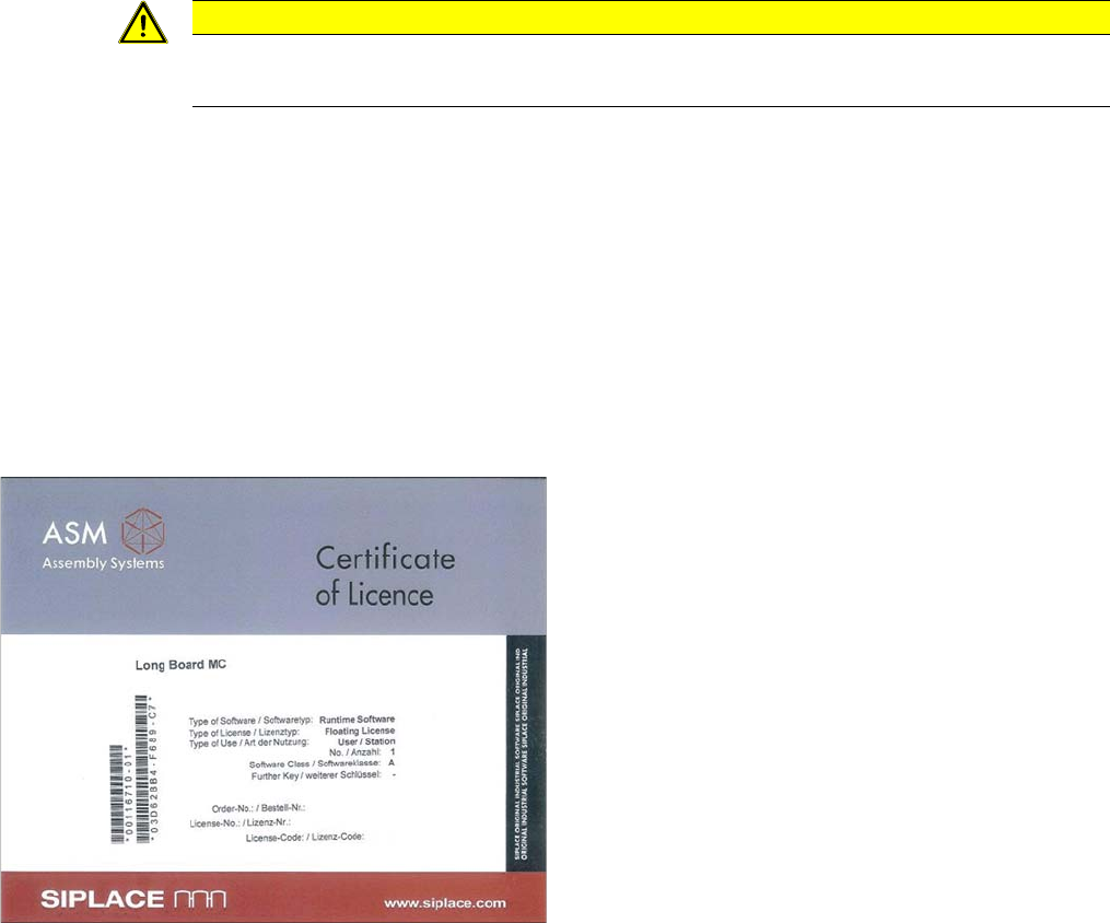
► Enable the license for this option on the SIPLACE-
PRO line computer. The license key can be obtained
from the ASM-AS internet license portal, using the
"Long Board MC" [00116710-01] certificate provided.
If you should have any questions about the license,
contact your SIPLACE Service team.