00197187-01_AI_LBO_SX12_ab_09-2011_FS02_de_en.pdf - 第48页
Fitting the Long Board Option Preparing the Stop Guide Rails 48 Long Board Option Overview Stop guide rail structure ► Dismantle the stop guide rails o n the upper and lower sections. T o do this, loosen the screws (5) a…
Fitting the Long Board Option
Overview
Long Board Option 47
3 Fitting the Long Board Option
3.1 Overview
3.2 Preparing the Stop Guide Rails
Overview of stop guide rail parts
NOTICE
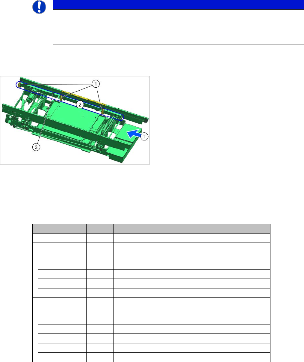
Single conveyor
Installation of the option is described below, using the example of a dual conveyor. Unless oth-
erwise specified, installation for a single conveyor is identical to that described for lane 1 of the
dual conveyor.
Overview of single conveyor SX1/SX2 (FS02)
1. Standard stopper
2. Sensor rail
3. Installation position of new stopper
T = transport direction
Item No. Quantity Designation
03088191-xx Stop guide rail left 599 complete
00200240-xx 7 Filister hex socket head screw (DIN-EN-ISO7380-M3x6-
12.9)
03064824-xx 2 Spring steel plate for height reference run
00317829-xx 2 Positioning fiducial
03088194-xx 1 Stop guide rail with rubber molding left 599
03088192-xx 1 Guidance rail left 599 (lower section)
03088196-xx Stop guide rail right 599 complete
00200240-xx 7 Filister hex socket head screw (DIN-EN-ISO7380-M3x6-
12.9)
03064824-xx 2 Spring steel plate for height reference run
00317829-xx 2 Positioning fiducial
03088199-xx 1 Stop guide rail with rubber molding right 599
03088197-xx 1 Guidance rail right 599 (lower section)
Fitting the Long Board Option
Preparing the Stop Guide Rails
48 Long Board Option
Overview
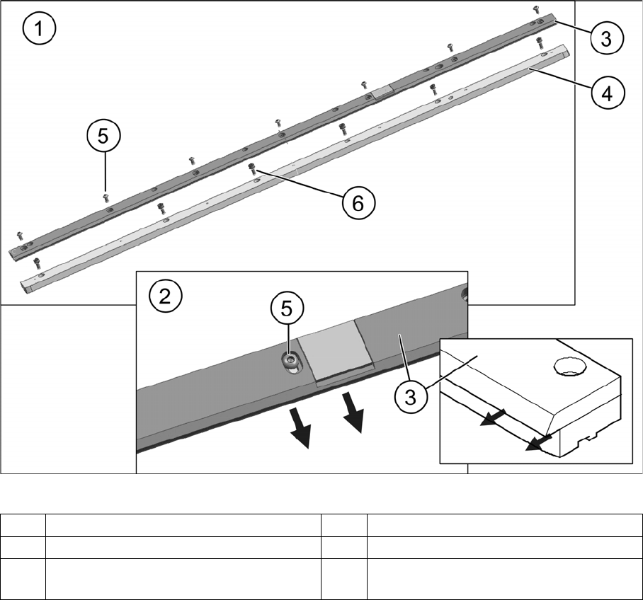
Stop guide rail structure
► Dismantle the stop guide rails on the upper and lower sections. To do this, loosen the screws (5) and
remove the upper section. Make sure that you keep the parts of the individual rails separate from
one another, to avoid subsequent confusion.
► Repeat these steps for all stop guide rails.
1 Stop guide rail, dismantled 2 Detailed view of stop guide rail
3 Upper section of stop guide rail 4 Lower part of stop guide rail
5 Filister hex socket head screw for fitting the
upper part to the lower part
6 Filister hex socket head screw for fitting the
rail to the conveyor side
Fitting the Long Board Option
Installing the Guidance and Stop Rails
Long Board Option 49
3.3 Installing the Guidance and Stop Rails
Overview
Installation
► Switch off the machine and secure it to prevent unauthorized reactivation. Observe the instructions
in section "1.2 Preparatory Work..." [ ➙ 37].
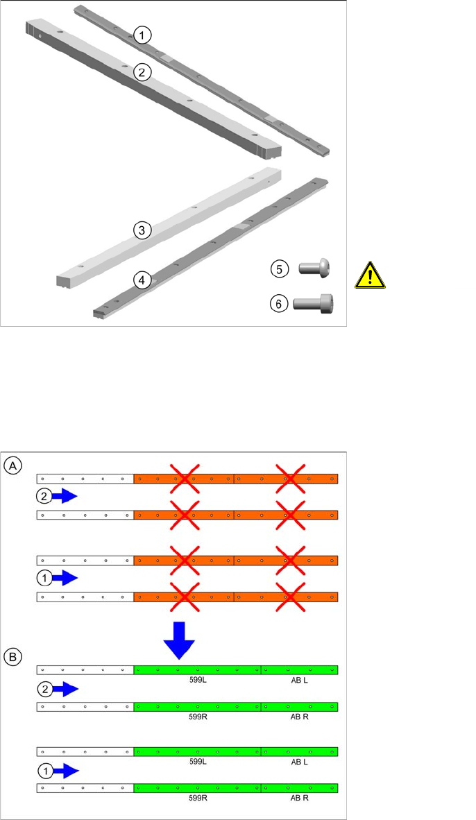
1. Stop guide rail (right) 599 complete [03088196-xx]
(incl. 7 screws (5))
2. Guidance rail AB R [03088180-xx]
3. Guidance rail AB L [03088179-xx]
4. Stop guide rail (left) 599 complete [03088191-xx]
(incl. 7 screws (5))
5. Filister hex socket head screw (DIN-EN-ISO7380-
M3x6-12.9) [00200240-xx] for fitting the stop guide
rail (7x per stop guide rail, prefitted)
6. Socket head cap screw (ISO4762-M3x8-A2-70)
[03042542-xx] for fitting the guidance rail to the side
If the screws are missing, use those from the old
guidance rails.
CAUTION!
Make sure you only use the filister hex socket head screw
when fitting the stop guide rail to the guidance rails. Any
other screws could cause a head crash!
Conversion of stopper, stop and guidance rails (not to
scale)
The diagram shows replacement of the stopper and guid-
ance rails, as described below.
A = dual conveyor without LBO
B = dual conveyor with LBO
1. Conveyor lane 1 or single conveyor
2. Conveyor lane 2