00197187-01_AI_LBO_SX12_ab_09-2011_FS02_de_en.pdf - 第54页
Fitting the Long Board Option Replacing the Lifting Table Plates 54 Long Board Option 3.6 Replacing the Lifting Table Plates ► Move t he conveyor s ystem to the maximum possible width. ► Loosen the screws fastening th e …
Fitting the Long Board Option
Fitting the Valve Unit
Long Board Option 53
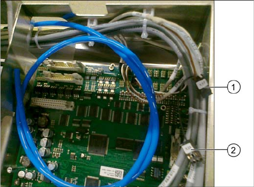
Connecting the valve unit to the TSP400
► Connect the cables to the TSP400 with the connec-
tors X37 (1) and X29 (2). This cable has been pre-run
and is already in the conveyor.
For an overview of connectors for TSP400, see section
"4.4 Conveyor Control TSP 400" [ ➙ 62].
Fitting the Long Board Option
Replacing the Lifting Table Plates
54 Long Board Option
3.6 Replacing the Lifting Table Plates
► Move the conveyor system to the maximum possible width.
► Loosen the screws fastening the two lifting table plates (4 x for each lifting table plate) and remove
the lifting table plates from the machine.
► Mark the positions of the lifting table plate fixtures to make it easier to refit them later on. Make sure
you do not confuse these.
► Now place the new (larger) lifting table plate onto the plate guidance.
► Fit the lifting table plate into place with the fastening screws. Adjust the edges to ensure that they
are parallel to the lifting table plate. (See "4.1 Setting the Parallelism and Height of the Lifting Table
Plate" [ ➙ 59])
► Dual conveyor: if the conveyor side clamps have been loosened, fix these again. Make sure that
the side edges are parallel.
CAUTION
Heavy machine part!
When removing the lifting table plates, remember that they are heavy. You may need to enlist
the help of a second person.
NOTICE
Single and dual conveyor
There is one lifting table plate in the single conveyor and two in the dual conveyor. Replacement
is described below, using the example of the single conveyor. For replacement in a dual con-
veyor, simple repeat the same steps for the second lifting table plate.
NOTICE
Move out conveyor sides, loosen clamps
Moving the conveyor sides to the maximum possible width is normally enough to allow room for
removing the lifting table plate from the conveyor.
In dual conveyors, you can also loosen the clamps for the relevant conveyor sides. These sides
can then be moved.
► (See section"4.3 Loosening the Conveyor Side Clamps (DT only)" [ ➙ 60].)
NOTICE
Single conveyor
The conveyor side clamps can only be loosened for dual conveyors. This is not possible for sin-
gle conveyors.
The flexible side of single conveyors can be moved when the machine is switched off, by care-
fully pulling on the width adjustment belt.
Fitting the Long Board Option
PCB Support
Long Board Option 55
3.7 PCB Support
When using the Long Board Option, the board inserted between the standard stopper position and the
LBO stopper position cannot be clamped along a length of approx. 60 mm. The use of a longer lifting
table plate provides support from below but there is still no clamping edge above, on the conveyor edge.
Special support pins are therefore required in this area.
Overview
Installing the PCB supports
► The required length of the PCB support depends on the expected warpage of the boards to be proc-
essed. Adjust the PCB supports so that any board warpage can be replicated. Position the pins (with-
out magnet protective disk) on a smooth surface and adjust the length with a caliper gauge.
► Begin with 2 PCB supports and set them to a total length of 94.2mm.
► Set the other PCB supports according to the expected warpage.
The length of the other PCB supports needs to be set according to the expected warpage of the
boards. (e.g.: 2x94.5 mm, 2x94.8 mm, 2x95.2 mm, etc.)
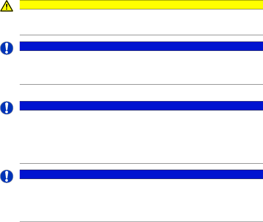
1. Spring-mounted PCB support 94 mm [03082256-xx]
2. Spring-mounted pin
3. Compression spring
This can be screwed into the compression spring
support with the M5 thread to adjust the overall length
of the PCB support. The spring force is 3 N (start) to
10 N (end).
4. Sleeve
This is used as a counter nut, to fix the compression
spring screwed in.
5. Compression spring support
6. Metal disk for protecting the magnets
This needs to be removed before use in the machine.
CAUTION
Remove the metal disk
Make sure that a metal disk is fitted to the underside of the PCB support, to protect the magnet.
► This metal disk needs to be removed before use in the machine!
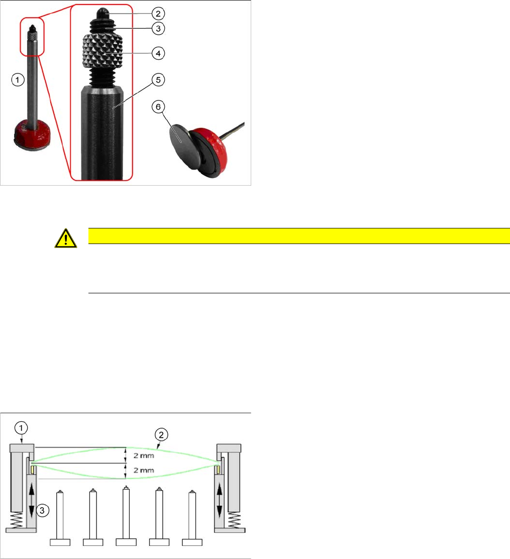
1. Fixed clamping edge
2. Board
3. Flexible clamping device