User-Manual-of-NeoDen4-PNP-machine.pdf - 第43页
38 1.Pick up posit ion 2.Gear 3. Plastic film fold back 4. Block Figure5.1 5.2 .2 Installing tube-fed components Install the Tube fe eder guide. This p olished ste el guid e is in cluded w ith th e machin e an d bolts to…
37
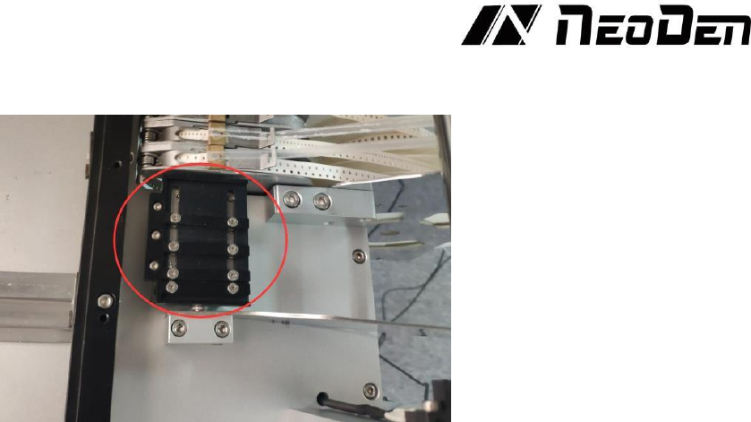
5.1.4 Vibration feeder
5.2
Installing SMT components
Three basic component setups are possible:
(1) Electric tape and reel feeding,
(2) Tube feeding and tray/short tape feeding. This section will cover the physicalsetup of each
type of component. Software setup of the various feeder types is covered in Section4.
5.2.1 Installing tape and reel components
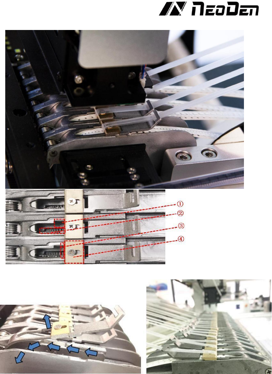
(1) Lift the angled tab on the feeder, and insert the tape so the sprocket holes rest on the tooth of
the gear. See the Figure 5.1.
(2) Pull the end of the cover tape through the large feeding slot in the feeder, over the brass block.
(3) Allow the spring to pull the feeder cover over the tape.
(4) Lift the silver tab on the peeler to separate the gears.
(5) Thread the cover tape through the slot on the angled tab, and through the gears on the peeler
until the tape extends through the back slot of the peeler. If the tape does not extend through the
whole peeler before the gears are closed, it will likely jam.
(6) Allow the spring in the peeler to close the plastic feeding gears.
Illustrates the proper installation of tape feeders.
38
1.Pick up position
2.Gear
3.
Plastic film fold
back
4.
Block
Figure5.1
5.2.2 Installing tube-fed components
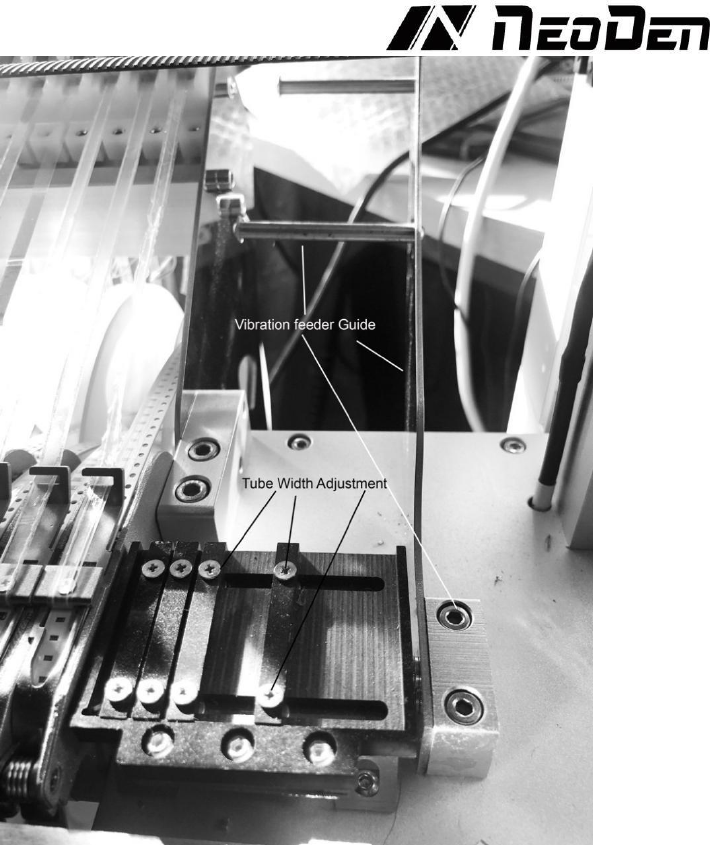
Install the Tube feeder guide. This polished steel guide is included with the machine and bolts to
the table with two Allen screws (included) as shown in Figure 5.2.
39
Figure 5.2
Screw the round horizontal tube guides into the plate as shown. These round guides will hold
pressure on the tube to maintain a good feeding angle and prevent movement.
Adjust the width of the black vibration feeder guides as necessary for each tube. If the tubes hold
very small components, it may be beneficial to use tape to cover the front slots between the black
guides.
Installing trays and short tapes. Trays and short tapes can be placed anywhere on the
table that is not in the space or path required by the board. If the width of the rail setting
necessitates removal of the left steel table extension (See Figure 2), first install a piece of metal or
plastic