User-Manual-of-NeoDen4-PNP-machine.pdf - 第44页
39 Figure 5. 2 Screw the ro und horizontal tube guides into the plate as s hown. These roun d guides will hold pressure o n the tub e to maintain a good fe eding an gle and p revent movement. Adjust the width of the blac…
38
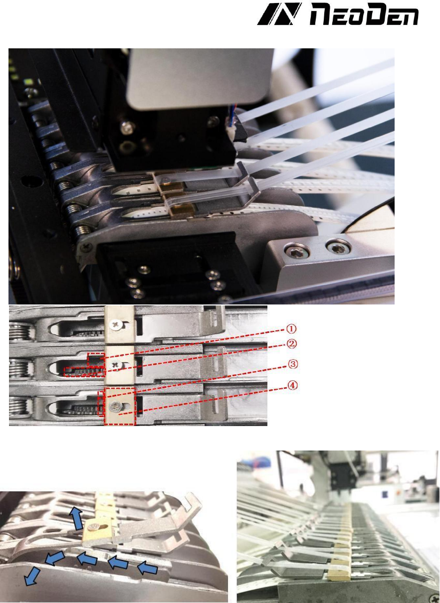
1.Pick up position
2.Gear
3.
Plastic film fold
back
4.
Block
Figure5.1
5.2.2 Installing tube-fed components
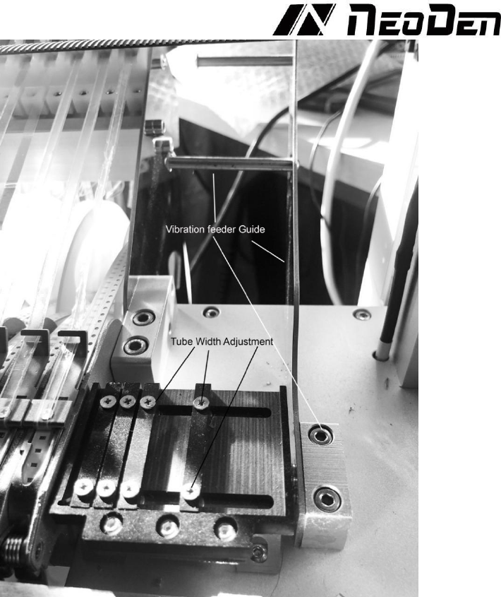
Install the Tube feeder guide. This polished steel guide is included with the machine and bolts to
the table with two Allen screws (included) as shown in Figure 5.2.
39
Figure 5.2
Screw the round horizontal tube guides into the plate as shown. These round guides will hold
pressure on the tube to maintain a good feeding angle and prevent movement.
Adjust the width of the black vibration feeder guides as necessary for each tube. If the tubes hold
very small components, it may be beneficial to use tape to cover the front slots between the black
guides.
Installing trays and short tapes. Trays and short tapes can be placed anywhere on the
table that is not in the space or path required by the board. If the width of the rail setting
necessitates removal of the left steel table extension (See Figure 2), first install a piece of metal or
plastic
40
sufficient to raise the height of the table to roughly the height of the extension. If the table extension
is installed, simply affix the tray or tape to the extension using double-sided tape or any other
suitable method. It is important that the components be placed in a reasonably straight horizontal or
vertical orientation, and that the tray or tape is placed flat to avoid variations in pick height. Figure 3
shows an example of a simple short tape/tray configuration.
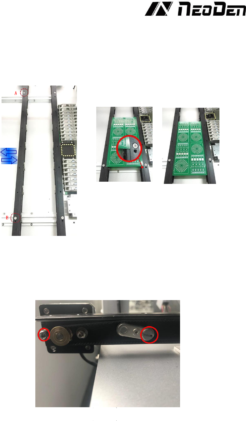
5.2.3 Auto-rails
Adjustment of auto-rails
Figure 5.3
Loosen screws on A and B, then the left rail can be moved arbitrarily.
Put PCB on the groove of rails and tighten and screws A and B once confirmed the width.
Once finished width adjustment, put the board into rails. See the Figure 5.3.
Adjustment of belt tightness
Loose the screw, move the motor up and down to adjust the tightness. Loose the screw, to adjust the
tightness, see the Figure 5.4.
Figure 5.4