User-Manual-of-NeoDen4-PNP-machine.pdf - 第8页
3 Figure 1. 2 Figure 1. position on the no zzle, very fine-pitch components (down to 0 201) ca n be p laced with repeatab le accura cy once th e correc t coord inates are identified. With the se ba sic unde rstandings, t…

2
1.2
Structure of NeoDen4
Design principles:
At the core, the NeoDen4 is a 4-axis Windows- controlled CNC with four separate vacuum nozzles,
each connected to its own vacuum pump. The machine employs a single X-Y coordinate system
covering the entire movement range of the head, which is 310x500mm. With resolution of .01mm
(10µm) and repeatability of .02mm (20µm), any X -Y coordinate can be identified as the location of a
feeder, the start of an array of components in a tray or short tape, a fiducial or the location at which a
component is to be placed on a circuit board.
Feeders and Nozzles:
Electric tape-and-reel feeders, vibration feeders and virtual tray feeders are all supported. Because of
the flexibility of the architecture, and the need to work with affordable quantities of parts, short tapes
can also be configured on the machine’s bed. Any size nozzle can be installed in any of the four
locations in the head, so a single machine can handle all of the necessary components without the
need for nozzle changes. The spring-loaded nozzles simply snap in and pull out of the head. Any
nozzle can be installed in any of the four locations on the head.
Number of Feeders:
The NeoDen4 can accommodate up to 48 8mm tape-and-reel feeders on its left and right rails, and
any size feeder (8, 12, 16 and 24mm) can be installed in any combination or order on the left and
right sides of the machine. The electric feeders are inexpensive but sophisticated microprocessor-
controlled units paired will tape peelers. In addition, the vibration feeder (included) can handle up to
5 separate tubes. The amount of space available for tray-fed components and short tapes depends on
the available real estate on the table. Any area of the table may be used for components awaiting
placement, or for the board under manufacture.
Component Thickness Limitations:
When using tray-fed and short-tape components, the maximum allowable component height is 5mm.
When using tape-and-reel components, we recommend a maximum thickness of 1.8mm for reliable
operation.
Rail system:
Machines equipped with the auto-loading rail system can accommodate boards from to in width, and
in length. Even when the rail system is installed, any space left over on the table is still available for
trays and short tapes. (The left rail can be moved to accommodate wide boards by removing the left
table extension. In this case, a block of material should be affixed to the table base to raise the tray or
short tape to the approximate height of the extension). The rail system allows automatic feeding of
PCBs, automatic alignment of the board with the camera, and automatic ejection from the front of the
machine or the rear. Rear-ejection is useful when the machine is connected to an optional conveyor
that can deliver the finished board directly to the reflow oven or to another NeoDen4.
Vision System:
The NeoDen4 features a high-precision, two-camera vision system. The cameras are made by Micron
Technology and are precisely aligned to the nozzles using the single unified configuration/operation
application that loads on power-on.
The downward-looking camera:
On the head is used for precision location of feeders and PCB placement points. The downward-
looking camera also verifies proper board placement (and compensates for minor board-position
inaccuracies) by auto-aligning the nozzles to multiple fiducials on the board before beginning actual
pick-and-place operations. Once the coordinates are established, the semi-closed-loop stepper motors
are able to repeat these locations to 20µm accuracy without further need for this camera.
The upward-looking camera:
located on the right side of the machine. When enabled, this camera first ensures that a component is
attached to the proper nozzle. If the camera detects the absence of a component, the machine will
make up to two additional attempts to pick a component before asking the user for further
instructions. Once a component has been verified as “picked”, the camera verifies its position relative
to the nozzle. Because SMDs are small and light, and are held only loosely in their packaging, there
can be a great deal of variation in the actual position of the component when it arrives in “pick”
position and is lifted by the nozzle. The vision system computes the difference between the ideal and
actual position (both X-Y and rotational), and then corrects for any error before precisely placing the
component. Because the vision system continually corrects for even small errors in component
3
Figure 1.2
Figure 1.
position on the nozzle, very fine-pitch components (down to 0201) can be placed with repeatable
accuracy once the correct coordinates are identified. With these basic understandings, the following
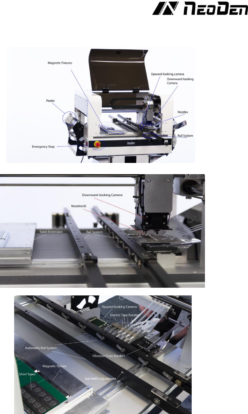
images reveal the basic components of the Neoden4, see Figure 1.1, Figure 1.2 and Figure 1.3.
Figure1.1
Figure1.2
Figure1.3
4
2.
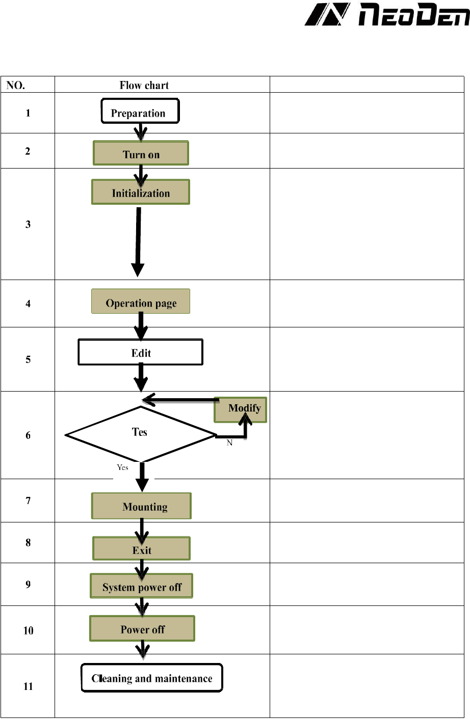
Operation Flow Chart
Note
Check the working environment whether it
is safe or not
The machine will start a 1-2 mins self-
inspection after boot-up. It enters the
operation page once finished. Need to wait
1-2 minutes after turn on the machine,
mounting head will move diagonally and
then enter into operation page
Please refer to the following pages about
detailed programming tutorial
After making a programming file, there
may exist several unpredictable problems,
such as rotation issues of components, so
a production testing is necessary for
solving issues.
Start to pick and place
Power off software
Power off after the software being turned
off, which decrease the damage to the
software
Keep the machine clean and nozzles need
to be washed regularly
Keep daily maintenance of nozzle assures
high utility.