TR7007M_SII_Hardware_en_v1-0-1.pdf - 第14页
Test Research, Inc. 4 TR7007 M SII User Guide – Hardware 3 H CI O PERA TING I NS TRU CT I ONS 3.1 Initial Screen Figure 3 below show s the St artup display. Pow er on the AOI system, wait approximately 5 seconds, and the…

Test Research, Inc.
TR7007M SII User Guide – Hardware 3
2 HCI & PLC
The Human-Computer Interface (HCI) is mainly used to set the required testing modes
(settings such as Stand-Alone or Inline, whether the Loader or Unloader are present, etc.).
The Programmable Logic Controller (PLC) is mainly used to control the PCB I/O Board
Holder as well as exchange sampling or Pass/Fail signals (through the RS-232 cable);
usually when the machine is set to In-Line mode there will be a greater chance of I/O board
issues or loader/unloader error. The function of HCI and PLC will be described in the
following chapters.
Test Research, Inc.
4 TR7007M SII User Guide – Hardware
3 HCI OPERATING INSTRUCTIONS
3.1 Initial Screen
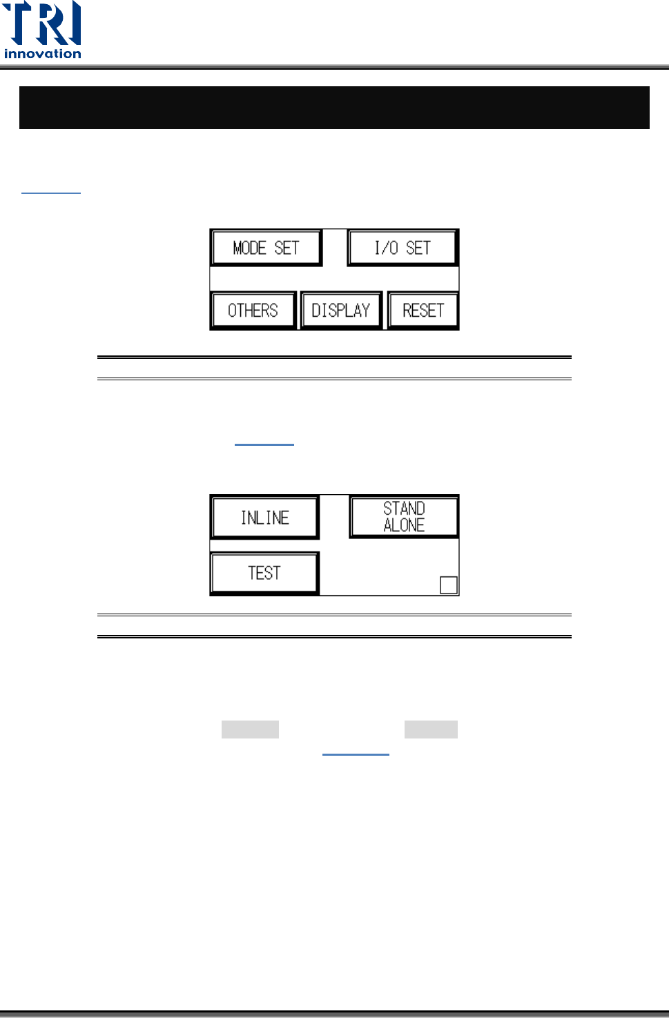
Figure 3 below shows the Startup display. Power on the AOI system, wait approximately 5
seconds, and the display will jump to the starting page. Five options will be shown:
Figure 3: Startup Display
3.1.1 Mode Set
After choosing [Mode Set] from Figure 3
the screen below will appear. Choose between
three modes: [INLINE], [Stand Alone ] or [ Test]. The setting will be automatically stored
during shut down, and automatically loaded at the next power on.
Figure 4: Mode Settings
INLINE: Connect to external manufacturing line equipment for inline inspection.
INLINE (hiding [BYPASS] button on Standby screen): Press and hold the hidden button at
the lower right corner of the display for at least 2 seconds, then press the [INLINE] button.
The button turns to black ([ INLINE]).Then, select the [INLINE] button to hide the
[BYPASS] button on the Standby screen (
Figure 37).
STAND ALONE: The TR7007 SII is not connected to external equipment for testing. This
mode requires manual loading and unloading.
TEST: Single board test, does not connect to external equipment for inline testing. User
may choose the number of test cycles.
3.1.2 I/O SET
Choosing different modes in MODE SET will result in different I/O settings. The settings are
explained in this section. Settings will be automatically stored during shut down, and
automatically loaded at the next power on.
Test Research, Inc.
TR7007M SII User Guide – Hardware 5
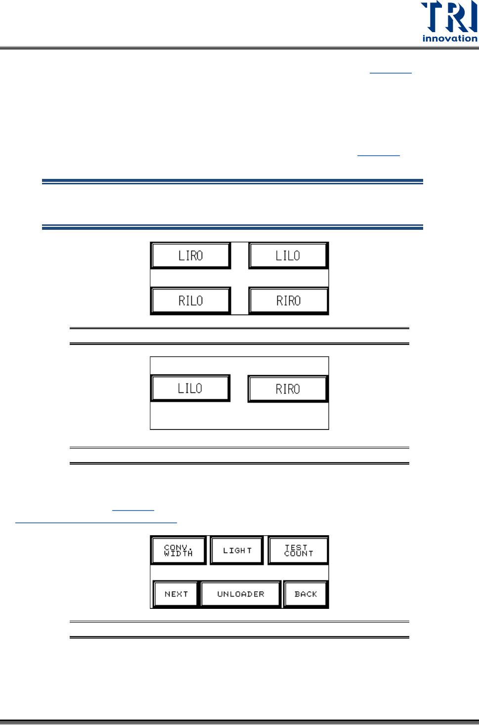
INLINE mode I/O SET: If Inline mode is selected, the display will show Figure 5, with four
options available: Left-In-Right-Out ([LIRO]), Left-In-Left-Out ([LILO]), Right-In-Left-Out
([RILO]) and Right-In-Right-Out ([RIRO]).
STAND-ALONE mode I/O SET: If Stand-Alone mode is selected, the display will show
four available options: [LIRO], [LILO], [RILO] and [RIRO].
TEST mode I/O SET: If Test mode is selected, the display will show Figure 6
, with two
options available: [LILO] and [RIRO].
NOTE: The factory default is Left-In mode, if the direction is changed to
Right-In mode, then Sensor2 (Brake Sensor) and Sensor 3 (Position
Sensor) positions and metal connectors need to be switched.
Figure 5: INLINE and STAND-ALONE Mode Settings
Figure 6: TEST Mode I/O Settings
3.1.3 Other Settings Page 1
At the Start screen (Figure 3
), if [OTHERS] is pressed, six options are available, as shown in
Figure 7: Other Settings Page 1.
Figure 7: Other Settings Page 1