TR7007M_SII_Hardware_en_v1-0-1.pdf - 第53页
Test Research, Inc. TR7007M SII User Guide – Hardware 43 7 L IGHTING T RIGGER B O AR D F UNCTION 7.1 Install USB Dri ver on PC If the driver has already been installed, this procedure can be skipped. 1) Link the cable fr…

Test Research, Inc.
42 TR7007M SII User Guide – Hardware
6.1.4 Power Board Layout
Figure 89: Power Board Layout
6.2 System Wiring Diagrams
For System Wiring Diagrams, please refer to the separate Wiring
Diagram manual.
Test Research, Inc.
TR7007M SII User Guide – Hardware 43
7 LIGHTING TRIGGER BOARD FUNCTION
7.1 Install USB Driver on PC
If the driver has already been installed, this procedure can be skipped.
1) Link the cable from PC USB to JA1, then PC will display “new hardware device”.
2) Choose to install the driver manually (CDM 2.02.04 WHQL Certified); the driver should be
installed twice.
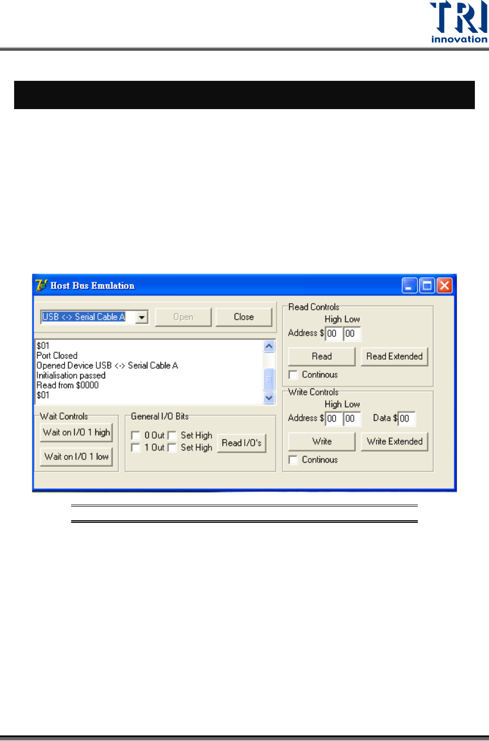
7.2 Function Test
Execute the test software FT2232C TEST TOOL\HostEmul.EXE.
Figure 90:Test Software – FT2232C Test Tool
7.3 Channel Trigger Variation
Cooperating with Camera Trigger Software
• Address = 0x0080 (Write) LED1&LED2
• Address = 0x0081 (Write) LED1&LED2
• Address = 0x0082 (Write) LED1&LED2
• Address = 0x0083 (Write) LED1&LED2
Test Research, Inc.
44 TR7007M SII User Guide – Hardware
Address
Data
LED1&LED2
00 80
01
LED1-off & LED-2-off
00 81
01
LED1-on & LED-2-off
00 82
01
LED1-off & LED-2-on
00 83
01
LED1-on & LED-2-off
Figure 91: Channel Trigger Variation
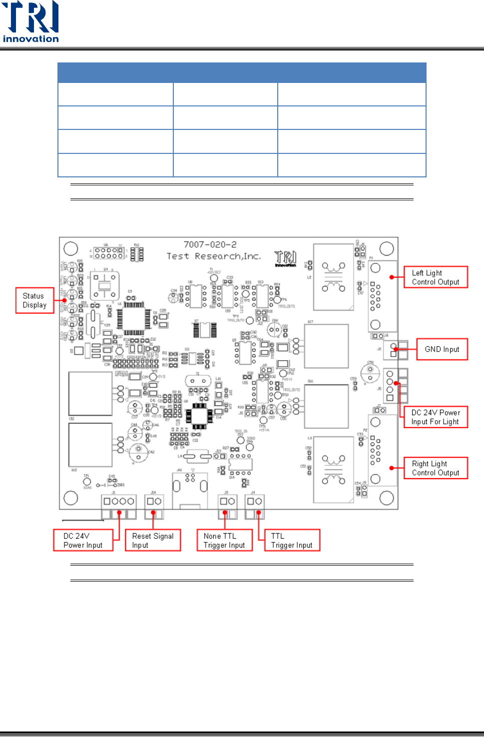
7.4 7007-020-2
Figure 92: 7007-020-2 Introduction