TR7007M_SII_Hardware_en_v1-0-1.pdf - 第48页
在线预览 TR7007M_SII_Hardware_en_v1-0-1.pdf PDF 文档。
Test Research, Inc.
TR7007M SII User Guide – Hardware 37
5 SUPPORT PIN
5.1 Architecture and Function
An external Support Pin is used with the HCI to set the Support Pin’s range of lift to
compensate for PCB board flex.
5.2 Installation
The Support Pin’s motor link wire and Sensor link wire are connected directly to the sockets
in the back of the machine (Sensor 7 and Width Control Motor). This completes the hardware
installation.
5.3 Configuration Procedure
Please refer to 3.2.5 Board Holder -Support Pin
5.4 Vacuum Support Pin Wiring Diagram
For System Wiring Diagrams, please refer to the separate Wiring
Diagram manual.
Test Research, Inc.
TR7007M SII User Guide – Hardware 39
6 MODULE BOARDS
6.1 Architecture & Function
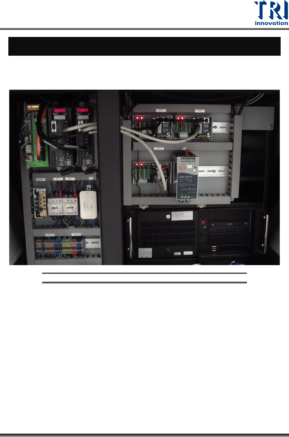
6.1.1 Front Module Board Layout
Figure 86: Front Module Board Layout