TR7007M_SII_Hardware_en_v1-0-1.pdf - 第68页
Test Research, Inc. 58 TR7007 M SII User Guide – Hardware Figure 104 : Conveyor Stepping Motor Driver 9.4.2 Replacement Driver: First turn off the power then remove the tw o sets of wires and two D C +24V power supply …
Test Research, Inc.
TR7007M SII User Guide – Hardware 57
9.4 Holder Motor
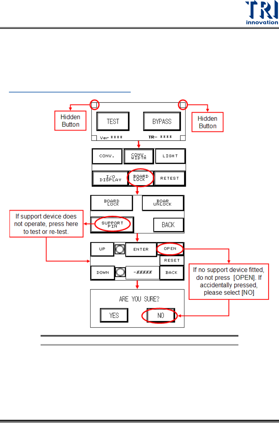
Elevation Motor Not in Position: First perform a test manually (press the two hidden buttons
simultaneously, the configuration procedure is shown in the figure below) to check if it is a
problem with the holder motor or with the support motor (if support device is not installed, do
not activate this option. If accidentally pressed, select NO). Observe the results and refer to
Figure 98: Motor Troubleshooting Matrix
to troubleshoot..
Figure 103: Holder Motor Troubleshooting Process
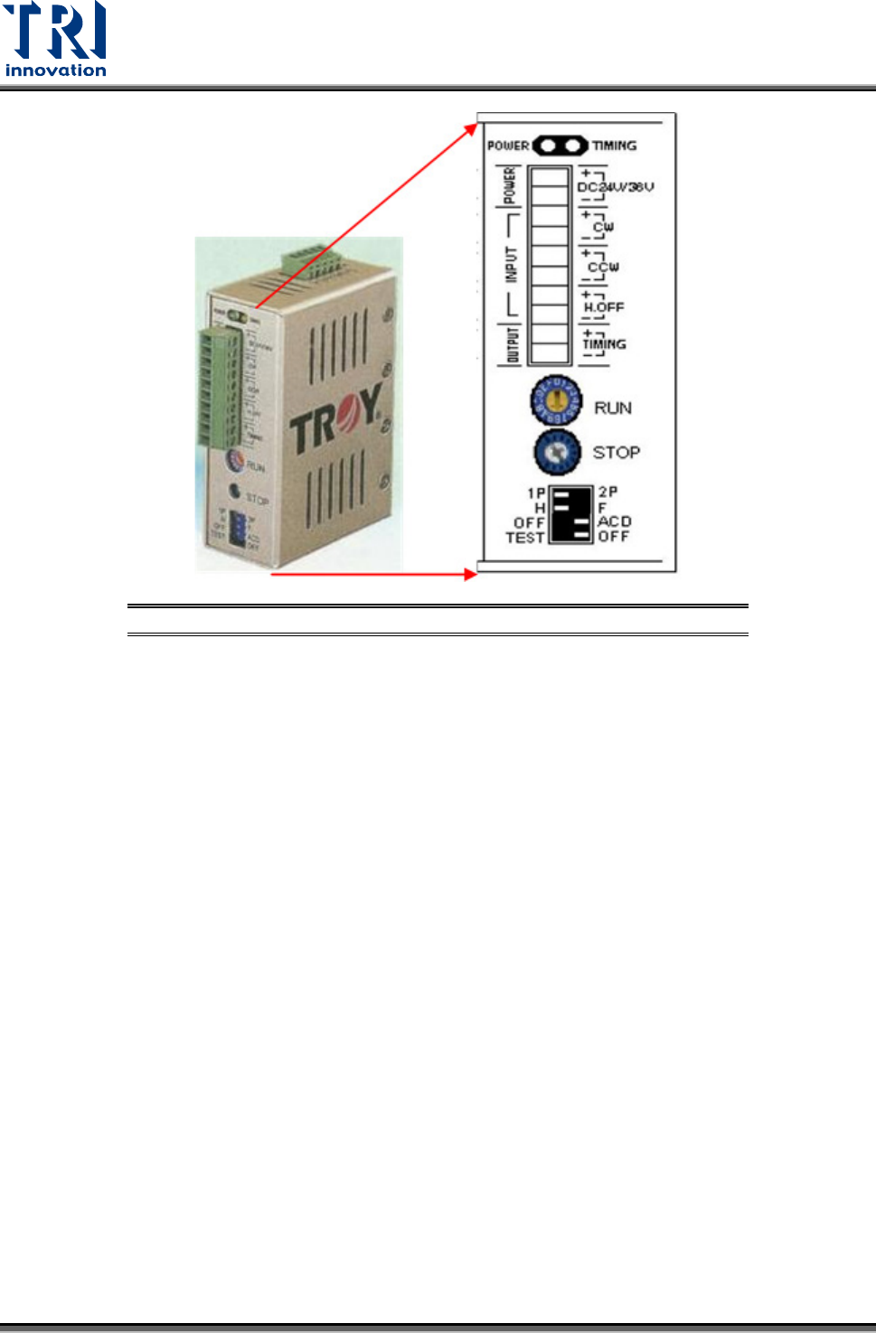
9.4.1 Step Motor Problem
There are two variable resistors located below the Driver. There is a cross-shaped location
where the variable resistor can be adjusted. Use the adjustment rod to turn the arrow at the
cross location, turn in a clockwise direction to increase. Check if the electric current of RUN
and STOP is adjusted to 80%.
Test Research, Inc.
58 TR7007M SII User Guide – Hardware
Figure 104: Conveyor Stepping Motor Driver
9.4.2 Replacement
Driver: First turn off the power then remove the two sets of wires and two DC +24V power
supply cables from the Driver. There is a screw at the top and bottom of the driver.
Remove the screws to install the new Driver. Once replacement is complete, reconnect
the wiring and power cables. After replacement re-adjust the driver using the proper
adjustment method.
Conveyor Motor: On top of the conveyor motor there is a clamped screw. Use a hex key
wrench to remove it, then insert the hex key wrench inside to unfasten the screw. Once
the screw is loosened the axle can be removed. Now unfasten the four screws around
the motor and remove the wire linking it to the machine. The motor can now be removed.
Test Research, Inc.
TR7007M SII User Guide – Hardware 59
9.5 INLINE Port
First check to see if it is the front or back stage that has the problem.
9.5.1 Front stage
LOADER: First highlight [BAR CODE], and if the board cannot be loaded that means there
is a problem with the Barcode settings in the main program. If the board still cannot be
loaded, this indicates a problem with the wiring.
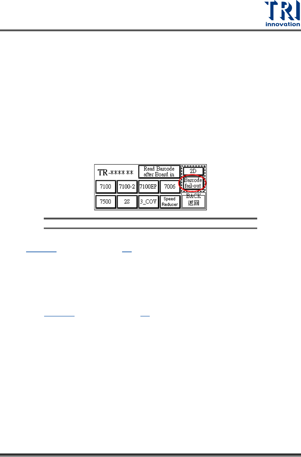
Inspect the Barcode Setting: [Barcode fail-out] Button (Disable/Enable): Refer to the
following figure. Highlight so the main program will not examine the barcode (do not wait
for the signal from the main program on PC for loading); Clear the highlight if it is to be
examined (wait for signal from the main program on the PC before loading). This option
works the same way for 1D or 2D Barcode settings.
Figure 105: Highlight Barcode Setting
Check if the cable connecting the front stage and the machine is properly connected (refer
to Figure 84). User also can refer 4.3
for the correct way to link to loader.
9.5.2 Back stage
Back stage is not ready.
Check if the cable connecting between back stage and machine is properly connected
(refer to Figure 84). User also can refer 4.3
for the correct way to link to loader.
9.6 X-Y TABLE ALARMS
X-Y table hardware error is indicated on the motor driver LED display as shown in the
following figure.. Press the FUNC button to toggle the display if necessary. In case of any
hardware error, see the corresponding Alarm code in the reference table below for
troubleshooting.
If no error code is shown on the LED display, but the X-Y table is still not functioning
properly, execute the EzLink software for diagnosis. If the EzLink can control the X-Y table,
there is no hardware problem and it might be a software problem, please contact TRI. The
procedure to confirm is described below.