TR7007M_SII_Hardware_en_v1-0-1.pdf - 第24页
Test Research, Inc. 14 TR7007 M SII User Guide – Hardware 3.1.4 DISPLAY A ll of the currently set m ode parameters can be viewed in Figure 33 and Figure 34 . Figure 33 : Displ ay M ode Param eters 1 Figure 34 : Displ ay …
Test Research, Inc.
TR7007M SII User Guide – Hardware 13
• [Speed Reducer]: Setting for speed reducer of Conveyor. (Only TR7500L/
TR7006LL)
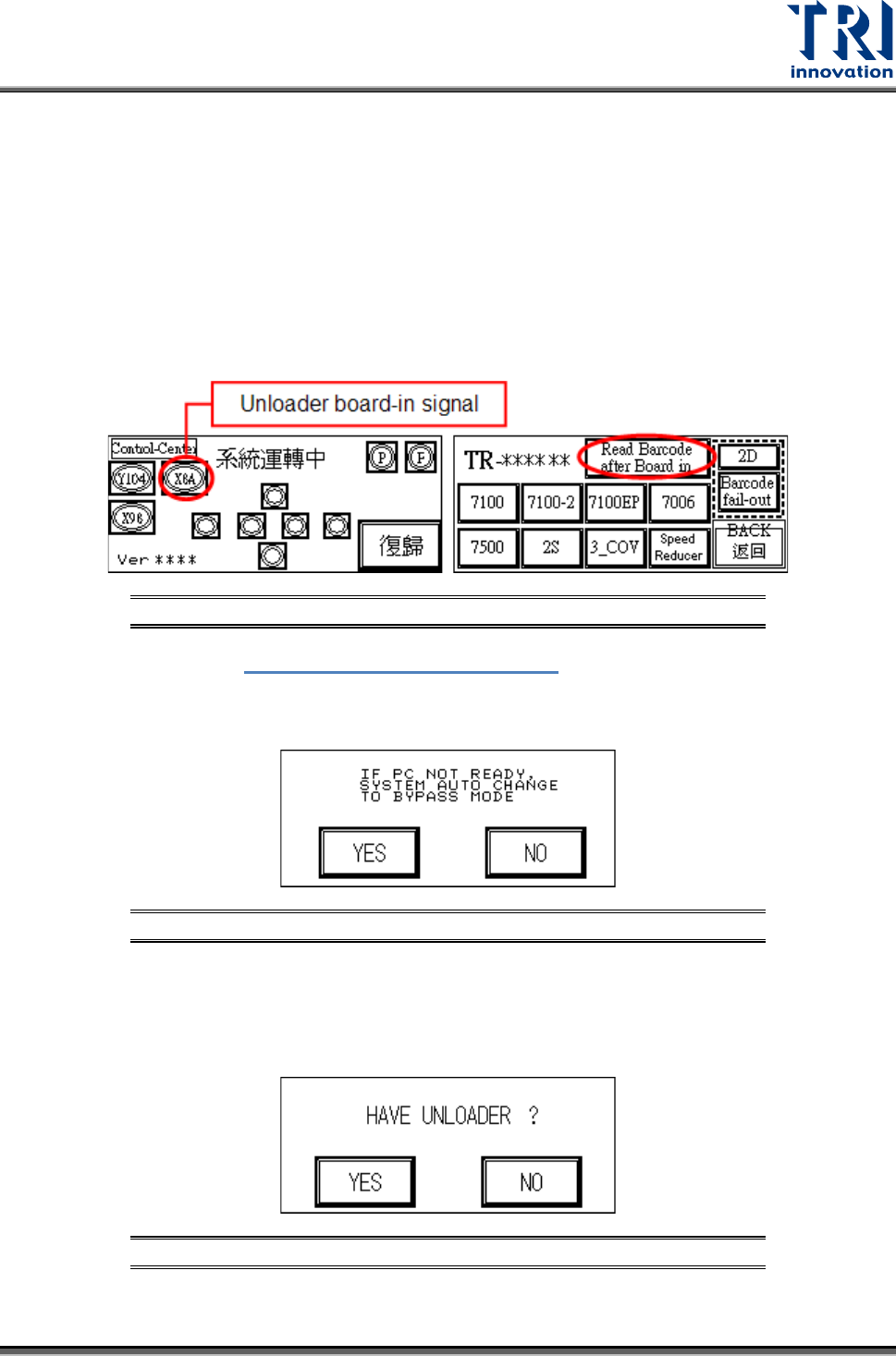
• [Read Barcode After Board in]: Pre-read setting of barcode. Link the red and
blue connector to the board-in signal of the loader to check if there is a signal
when board is ready. When [Read Barcode After Board in] is selected and the
original barcode button changes to select [barcode fail], the board will stop
outside the machine (Sensor 1) or stop inside the machine (Sensor 4). The
stop alarm is decided by the main PC (main program). The barcode reader is
triggered just when the former board is inspected completely, that is to
prevent the time to read barcode ifrom being too short.
Figure 30: Barcode Pre-read Setting
BACK: Return to Figure 18: Other Settings Page 2.
BYPASS: Confirm that when the PC is not ready, the PLC will automatically change to
Bypass Mode to avoid Loader blockage.
Figure 31: Confirm Auto-Change to Bypass Mode
UNLOADER: Choose if there is an Unloader. In Inline mode, once a test is completed and
the Unloader sends a READY signal then the board will automatically be unloaded. If
there is no Loader, once the test is completed the board will stop at the exit and wait for
manual removal before processing the next board.
Figure 32: Confirm Unloader Present
BACK: Go back to the Figure 3 Startup screen.
Test Research, Inc.
14 TR7007M SII User Guide – Hardware
3.1.4 DISPLAY
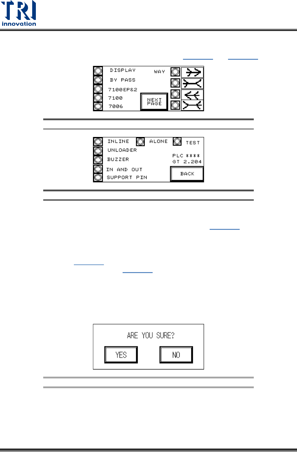
All of the currently set mode parameters can be viewed in Figure 33 and Figure 34
.
Figure 33: Display Mode Parameters 1
Figure 34: Display Mode Parameters 2
3.1.5 RESET
After pressing [RESET] the screen will show a confirmation dialog (Figure 35
). Once reset
has been completed testing will begin.
RESET Confirmation
If [YES] is pressed in Figure 35
then the Reset operation will be executed, and the display
will show that the system is resetting (Figure 36). If [NO] is pressed then it will return to the
previous display.
Upon the initial power up of the machine or after an emergency system shutdown, the Reset
action will return the X-Y Table to the original position and move the PCB to the unload end
(depending on the direction set). In other situations the X-Y Table will not move but the PCB
will still be moved to the unload end.
Figure 35: Confirm Reset Screen
Test Research, Inc.
TR7007M SII User Guide – Hardware 15
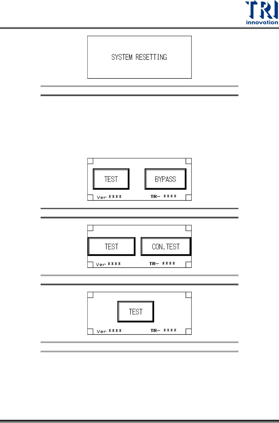
Figure 36: System Resetting Screen
Start TEST
1) Standby Screen: Once the system reset has been completed, if the mode is set to Inline
then the display will show two options: [TEST] and [BYPASS] (below). If the mode is set
to Stand-Alone mode then the display will show two options: single [TEST] and
[CONTINUOUS TEST]. If the mode is set to TEST mode, then the display will show only
the start TEST option.
Figure 37: Inline Mode Test Screen
Figure 38: Stand-Alone Mode Test Screen
Figure 39: TEST Mode
2) Start TEST
Press [TEST] under Inline and Stand-Alone mode to begin testing, the display will show that
the system has begun AOI testing; press [TEST] under Test mode and the display will show
the number of tests performed so far.