TR7007M_SII_Hardware_en_v1-0-1.pdf - 第45页
Test Research, Inc. TR7007M SII User Guide – Hardware 35 different due to differences in manufacturer, cont act the front stage manu facturer to acquire the connection data.) The standard SMEMA si gnal lin k scheme is sh…
Test Research, Inc.
34 TR7007M SII User Guide – Hardware
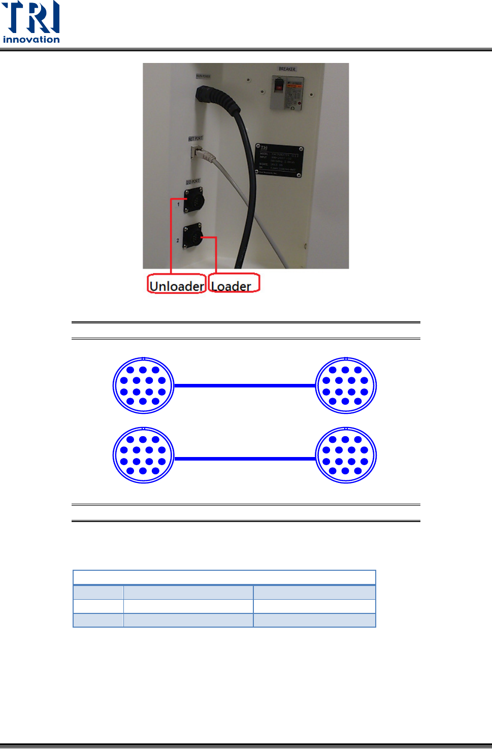
Figure 83: Loader and Unloader Socket Position
Figure 84: Loader and Unloader Cable
4.3.2 Unloader Connection
PORT2 – DOWN LINE
X98
Black (1) / Green (2)
Ready
Y106
Red (3) / Blue (4)
Board Available
Y105
Yellow (5) / White (6)
OK: Short; NG: Open
Located below the power supply socket in the back of the equipment is I/O PORT2. Connect
the connector, and there are three sets of different colored wire pairs at the connector end.
These are: Black-Green (X98) for receiving READY board request signal from the Unloader,
Red-Blue (Y106) board unload signal to the Unloader and the Yellow-White (Y105) TEST
PASS signal connector. Connect the Black-Green connector with the Unloader’s connector
for sending READY board request signal. Then connect the Yellow-White connector with the
Unloader TEST PASS signal receiving signal. (We use the standard SMEMA signal. If this is
PIN1~PIN6
1 2 3
4 5 6 7
8 9 10 11
12 13 14
PIN1~PIN6
1 2 3
4 5 6 7
8 9 10 11
12 13 14
1 2 3
4 5 6 7
8 9 10 11
12 13 14
1 2 3
4 5 6 7
8 9 10 11
12 13 14
Test Research, Inc.
TR7007M SII User Guide – Hardware 35
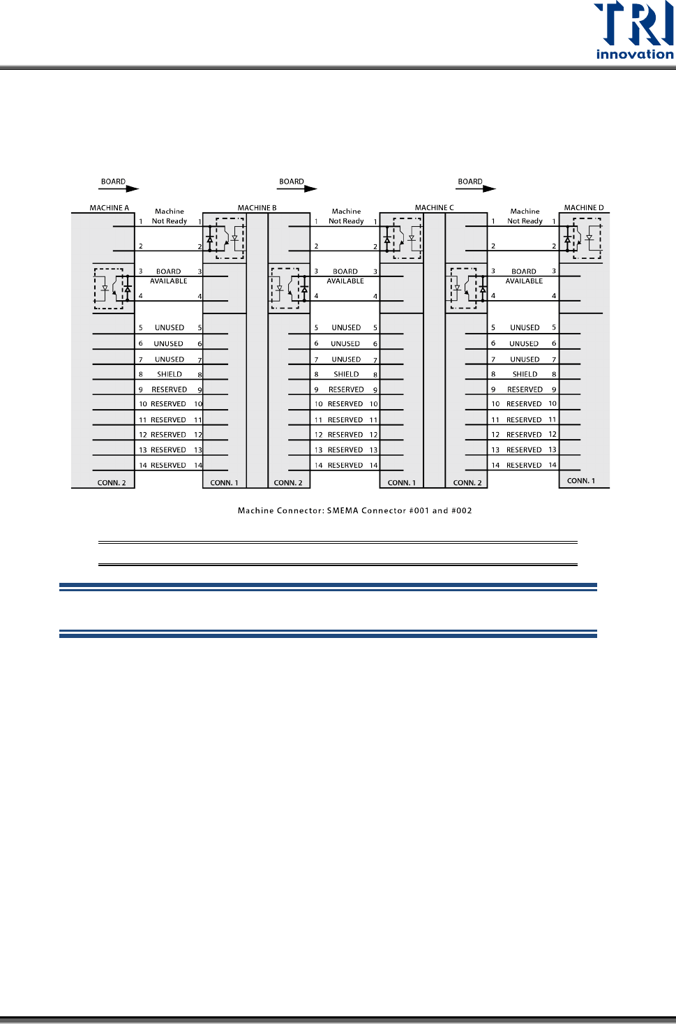
different due to differences in manufacturer, contact the front stage manufacturer to acquire
the connection data.)
The standard SMEMA signal link scheme is shown in the figure below.
Figure 85: Standard SMEMA signal link
NOTE: The above connections are all single point relays so there are no
positive or negative polarity differences.