TR7007M_SII_Hardware_en_v1-0-1.pdf - 第65页
Test Research, Inc. TR7007M SII User Guide – Hardware 55 Figure 101 : Sensor Adjustment Sensors 5 & 6: Lower th e holder mechanism to its lowest position along w ith t he Sensor as well. Mov e the Sensor upwards un…
Test Research, Inc.
54 TR7007M SII User Guide – Hardware
9.3 Conveyor Belt
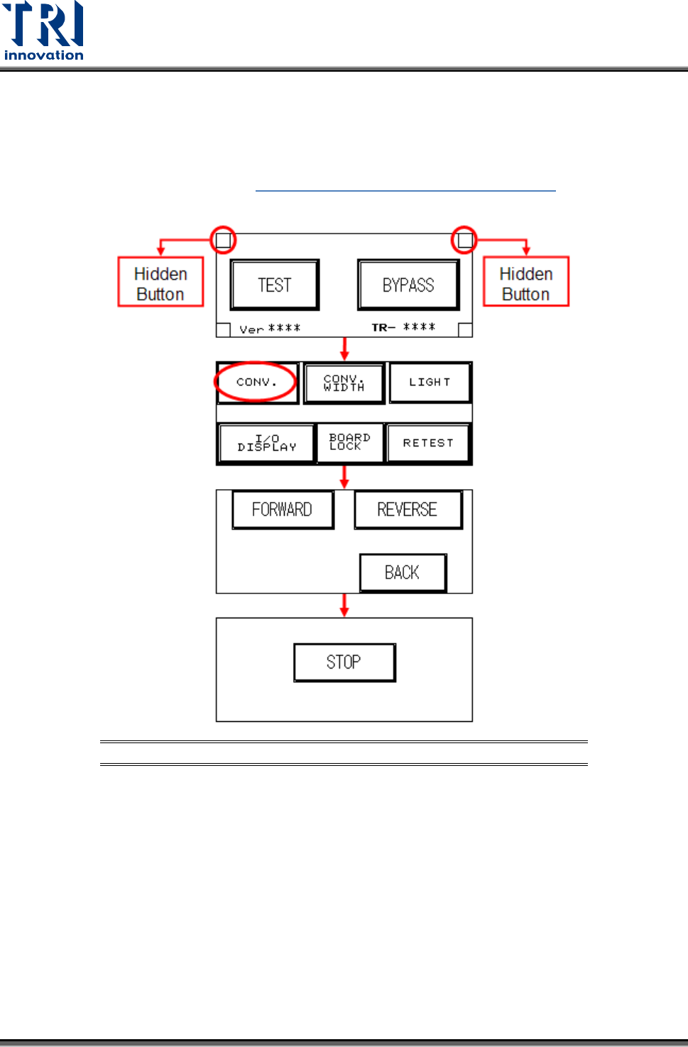
If there is a Sensor or Conveyor problem, perform a test manually (the two hidden buttons
must be pressed simultaneously, the setting procedure is as shown in figures below) and
depending on the results, refer to Figure 98: Motor Troubleshooting Matrix
and
troubleshoot.
Figure 100: Sensor/Conveyor Troubleshooting Process
9.3.1 Sensor Problem
-
Adjustment
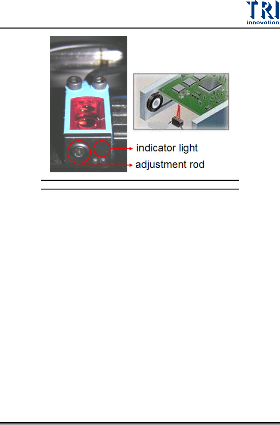
Sensor 1 & 2 & 4: Place the candidate board on the Sensor to be tested, and use the
adjustment rod to adjust the Sensor’s optimal detection range. When there is a candidate
board waiting to be tested over the Sensor, the Sensor’s indicator light will glow red. If
there is no candidate board over the Sensor, the indicator light will turn off.
Test Research, Inc.
TR7007M SII User Guide – Hardware 55
Figure 101: Sensor Adjustment
Sensors 5 & 6: Lower the holder mechanism to its lowest position along with the Sensor
as well. Move the Sensor upwards until the indicator light is lit, then move it slowly
downwards again until the indicator light goes off for the correct setting.
If there is no response from the Sensor, first re-adjust the Sensor sensitivity. If there is
still no response, do not attempt repair, replace with a new Sensor. Replacement
Method: first disconnect the Sensor connector, and then remove the Sensor. Attach the
new Sensor then connect and secure the Sensor’s connectors. Once replacement is
complete, adjust as directed in the adjustment method.
9.3.2 Step Motor Problem
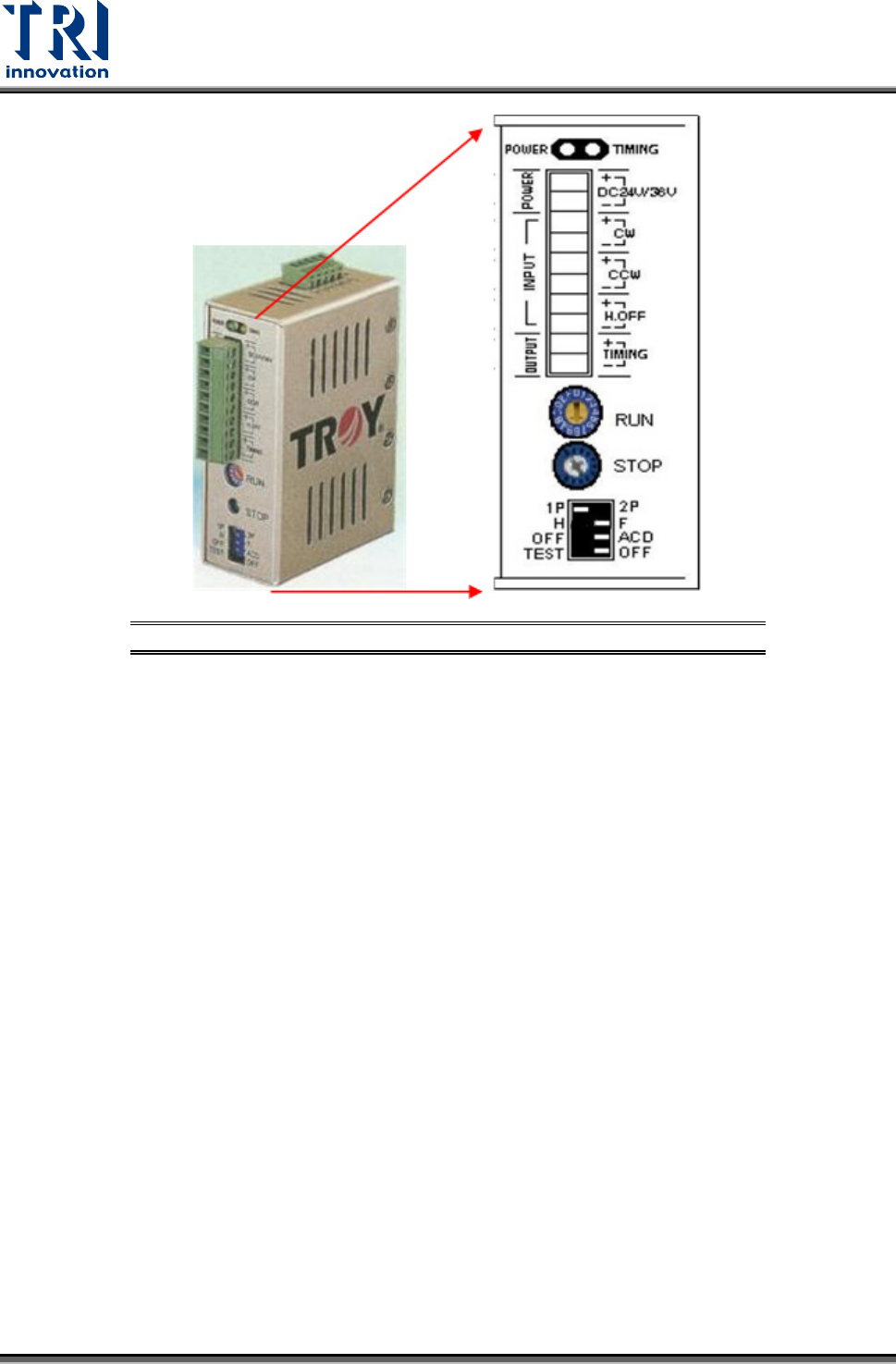
There are two variable resistors located below the Driver. There is a cross-shaped
location where the variable resistor can be adjusted. Use the adjustment rod to turn the
arrow at the cross location, turn in a clockwise direction to increase. Check if the electric
current of RUN and STOP is adjusted to 80%.
Test Research, Inc.
56 TR7007M SII User Guide – Hardware
Figure 102: Conveyor Stepping Motor Driver
9.3.3 Replacement
Driver: First turn off the power then remove the two sets of wires and two DC +24V power
supply cables from the Driver. There is a screw at the top and bottom of the driver.
Remove the screws to install the new Driver. Once replacement is complete, reconnect
the wiring and power cables. After replacement re-adjust the driver using the proper
adjustment method.
Conveyor Motor: On top of the conveyor motor there is a clamped screw. Use a hex key
wrench to remove it, then insert the hex key wrench inside to unfasten the screw. Once
the screw is loosened the axle can be removed. Now unfasten the four screws around
the motor and remove the wire linking it to the machine. The motor can now be removed.